I designed in this a few years ago and published it under a creative commons license so that people could print their own. Here is some information I wrote back in 2014:
Download here:
Design
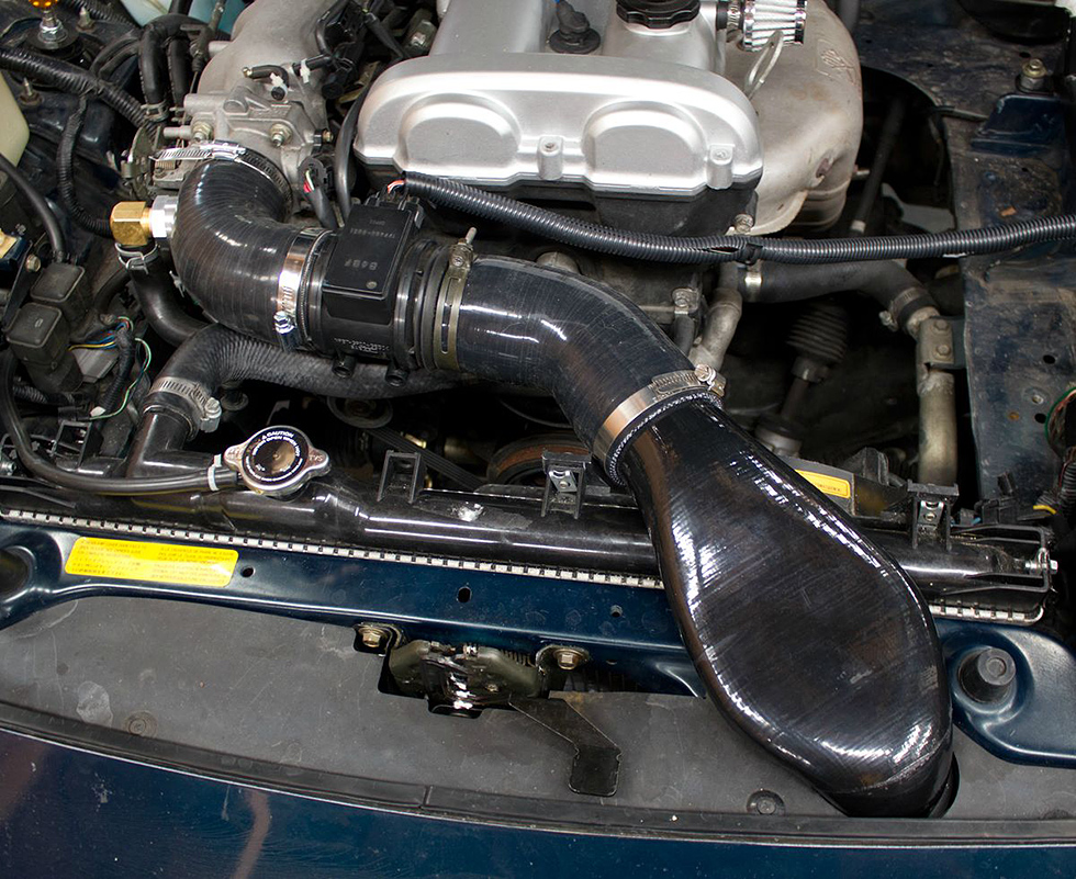
The goal of this intake system is draw ambient air into the engine while getting close to ideal intake tract length. The duct routes through the negative space in front of the radiator and then through a factory hole in the radiator support bar. This fits miatas from 1994 to 1997 running stock engine managment or all years of first generation miatas running a MAP based ECU (the 1.6l air flow meter will not fit where the MAF goes).
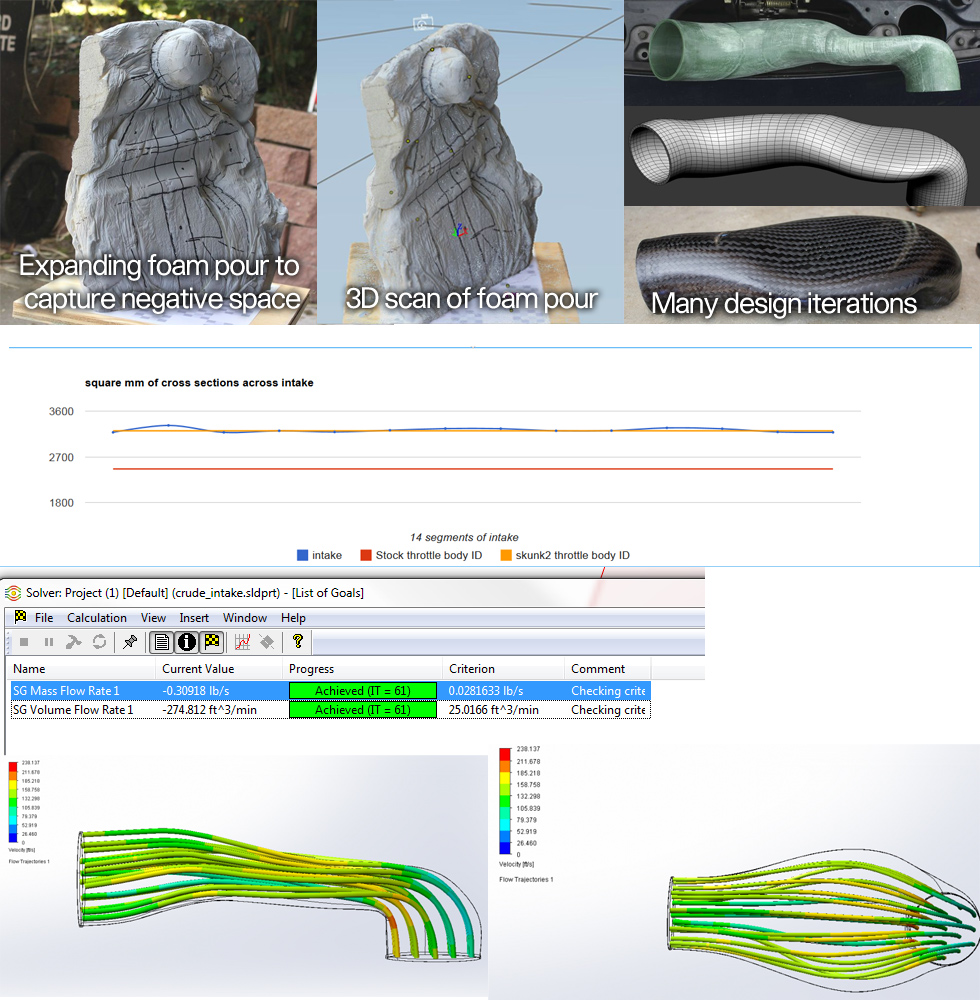
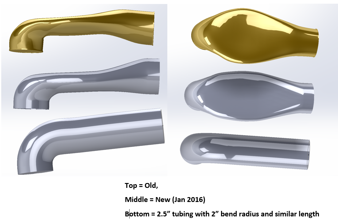
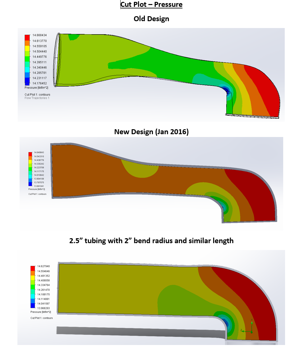
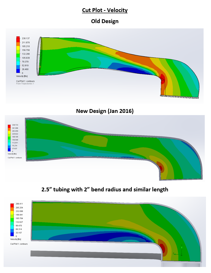
The design started with a urethane expanding foam pour to capture the availible negative space, that was 3d scanned and I have made about a dozen design iterations over the course of 9 months. I was careful in the design to make smooth transitions between shapes and keep a very consistent cross sectional area at every point of the duct. Cyotani on miataturbo volunteered to CFD simulations on the part (pictured) and came up with a pressure drop of .2 PSI at 275cfm. The intake has an internal dimeter of 62mm and is approxiamtely 25″ long from the tip of the throttle body to the edge of the filter flange. There is a thread on miataturbo showing most of the build process Here.
The files are all availible under a creative commons license that allows people to share and adapt the design so long as they attribute appropriate credit and do not use it for commercial purposes.
This work is licensed under a Creative Commons Attribution-NonCommercial-ShareAlike 4.0 International LicenseDownload Version 1.0 7/18/2014
Getting It Printed
Print cost is hugely variable depending on who is doing the printing and in what material. Most commercial printing services won’t be affordable. All of my prints have been done in multiple sections and I bond them using ABS cement (MEK solvent with ABS filler material, commonly found in the plumbing section of HD). ABS plastic is the only material I have tested this with and is the only commonly available FDM filament that I would use. PLA plastic will almost definitely melt or deform.
I strongly reccomend getting an acetone vapor polish done on the part. My break tests have shown a big improvment in strength between parts that are and aren’t treated this way. The blue part pictured on the left hasn’t been acetone vapor polished. It is much easier to delaminate the layers and break the part.
Required Parts
This intake is designed around 2.75″ tubing- this size is the easiest to mate to the stock MAF and it is a good match for more reliable aftermarket throttle bodies. The intake’s internal cross section is 62mm which is larger than the stock throttle body and very close in size to skunk2 64mm throttle body.
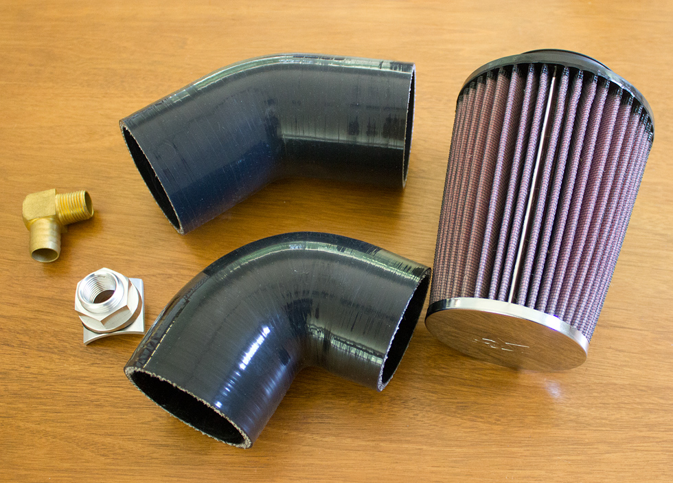
Couplers:
I bought all my couplers from www.siliconeintakes.com. I have ordered a few ebay elbows, some of them have been off by as much as 10 degrees and made fitting difficult.2.75″ 45 degree elbow
2.75″ to 2.5″ 90 degree reducing elbow (if using a 64mm throttle body)Fitting for IACV hose (not needed for NB engine swap):
Silicone intakes port system
90 degree 1/2″ NPT to 3/4″ hose barbAir filter:
I designed this around the K&N RC-9310. This filter is expensive but it is a very good fit for the space and I optimized the duct length to match the length of the filter flange. There are other air filters out there that will fit but the critical limiting factors are that it needs to have 2.75″ flange and be no more than 4.75″ in diameter. A 5″ diameter filter will not fit the availible space and you will have to force it through bumper opening or remove the undertray to install.
You also need a small filter for the crankcase breatherFor cars running stock engine management this is all you need. For cars running MAP on an aftermarket computer you will also need a 5.5″ length of 2.75″ tubing and some provisions for placing an IAT sensor. I found an aluminum tube caused severe IAT sensor heat soak.
Making It Fit
1) Bend or remove hood prop for clearance. The hood prop still works when bent but the intake prevents you from being able to use it.
2) install 90 degree elbow on throttle body and mark location to cut hole for IACV fitting. Install port system and fitting.
3) Trim or remove plastic clip that runs through the bumper support just to the left of main hole. This clip holds a plastic bracket for the hood release cable. The hood release works just as well with the bracket floating.
4) Some years have horn wiring routed on top of the bumper support, if so reroute it under the support out of the way.
5) With plastic cooling shroud in place, run a razor blade along the factory hole to make clean trim.
6) Insert the duct, and mock up placement of elbows and maf.
7) For users running stock engine managment, extend the MAF wiring so that the connector will reach.
8) Disconnect the duct from the 45 degree elbow but leave it in place. Slip the filter over the duct by working it left to right. Do not press too hard on the ABS plastic- it is brittle and can crack. This can be done through the bumper opening with the car on the ground but it is much easier (especially the first time) with the car a few feet off of the ground and with the plastic undertray removed. I usually use a short ratchet with a socket matching the hose clamp.
9) Re-fit the 45 degree elbow. Before adding any clamps adjust rotation and position of pieces for best fit.
10) Lower the hood and gently press down for it to latch. If you feel abnormal resistance stop and make sure your hood latch isn’t out of adjustment.
11) Attach breather filter to crankcase, add hose clamps and tighten everything.

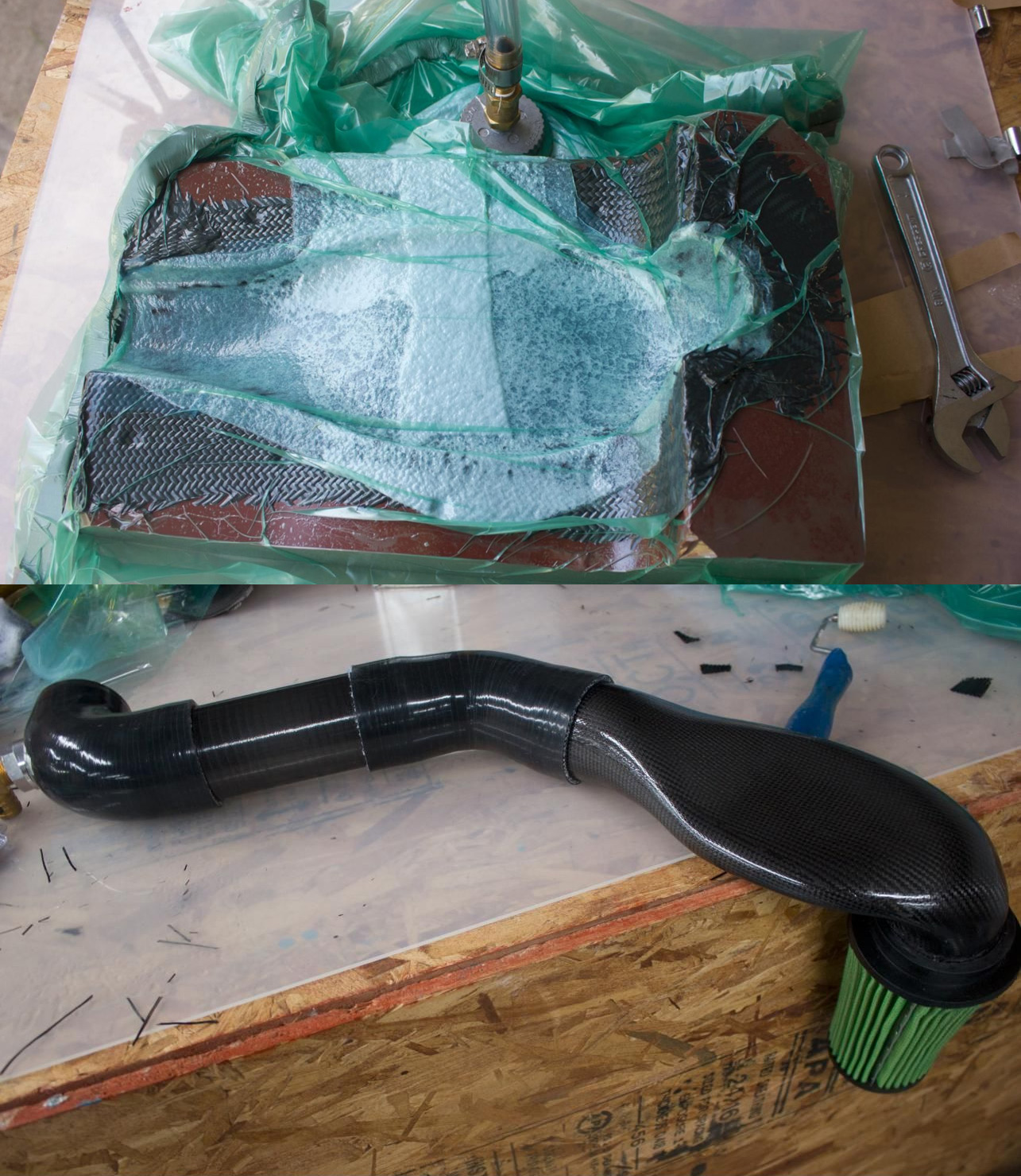
In 2016 I did a redesign that flows about 12% better but requires a very thin wall thickness. It can’t be easily printed but I will be making some carbon fiber versions off of the updated design and I will post about that process when I do.
Hello!
Sorry for my bad english!
I want to know if you still produced this intake 3D printed for 95 NA8 Miata?
What will be the prize? I read on different forums, around 300$, is it true?
Thanks you man!