When developers are building a car for a racing game they’re are primarily concerned with the body work and the interior. Some amount of effort goes into modeling the mechanicals of the car but those are only seen from suspension cams, when then the car flips, and they’re always shown in an assembled state. There are no bolt holes, no bolts, and the mechanicals are necessarily simplified and inaccurate. It would be a huge waste of production resources to build every component of the car as a standalone object and then make it all fit together.
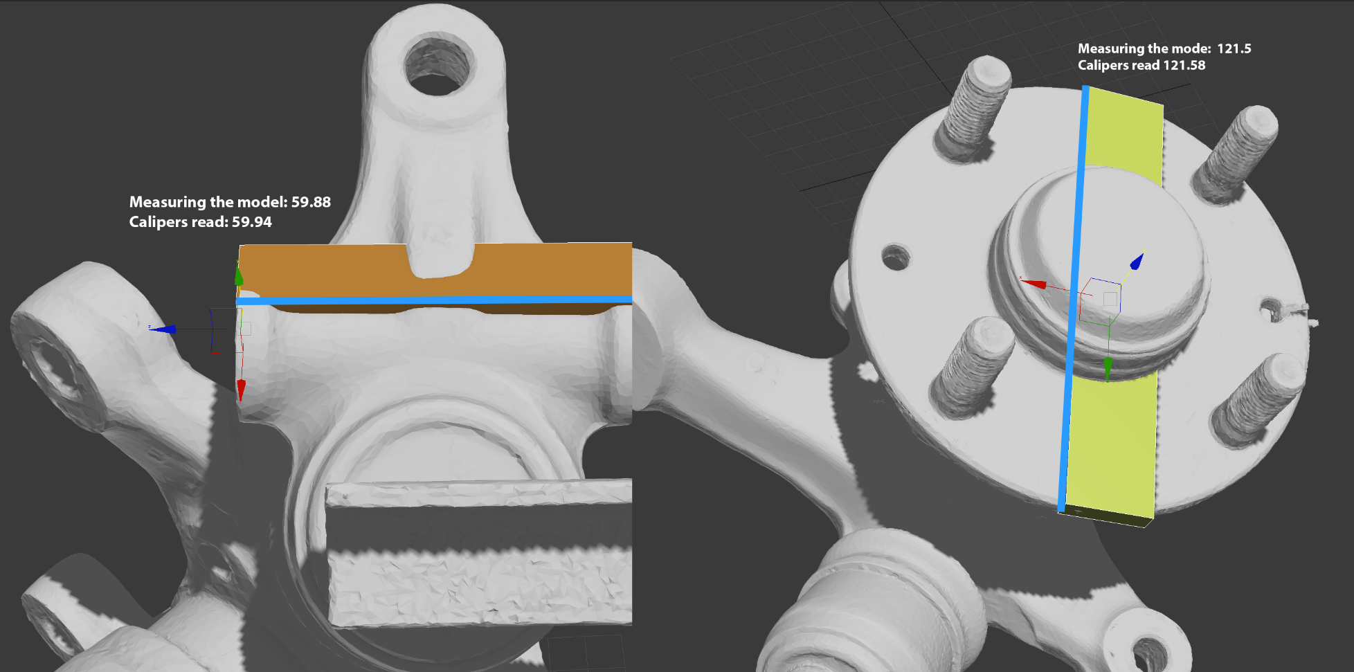
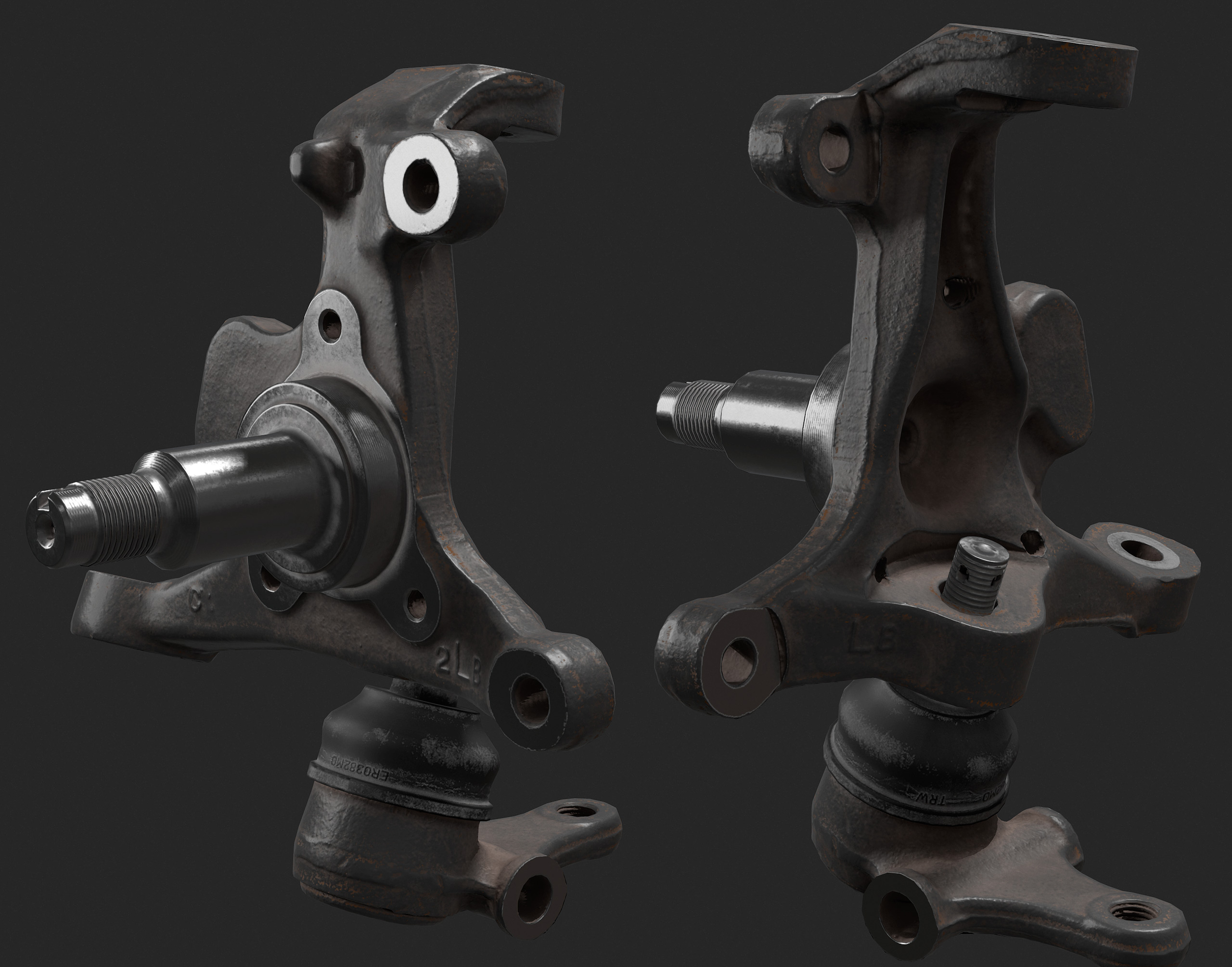
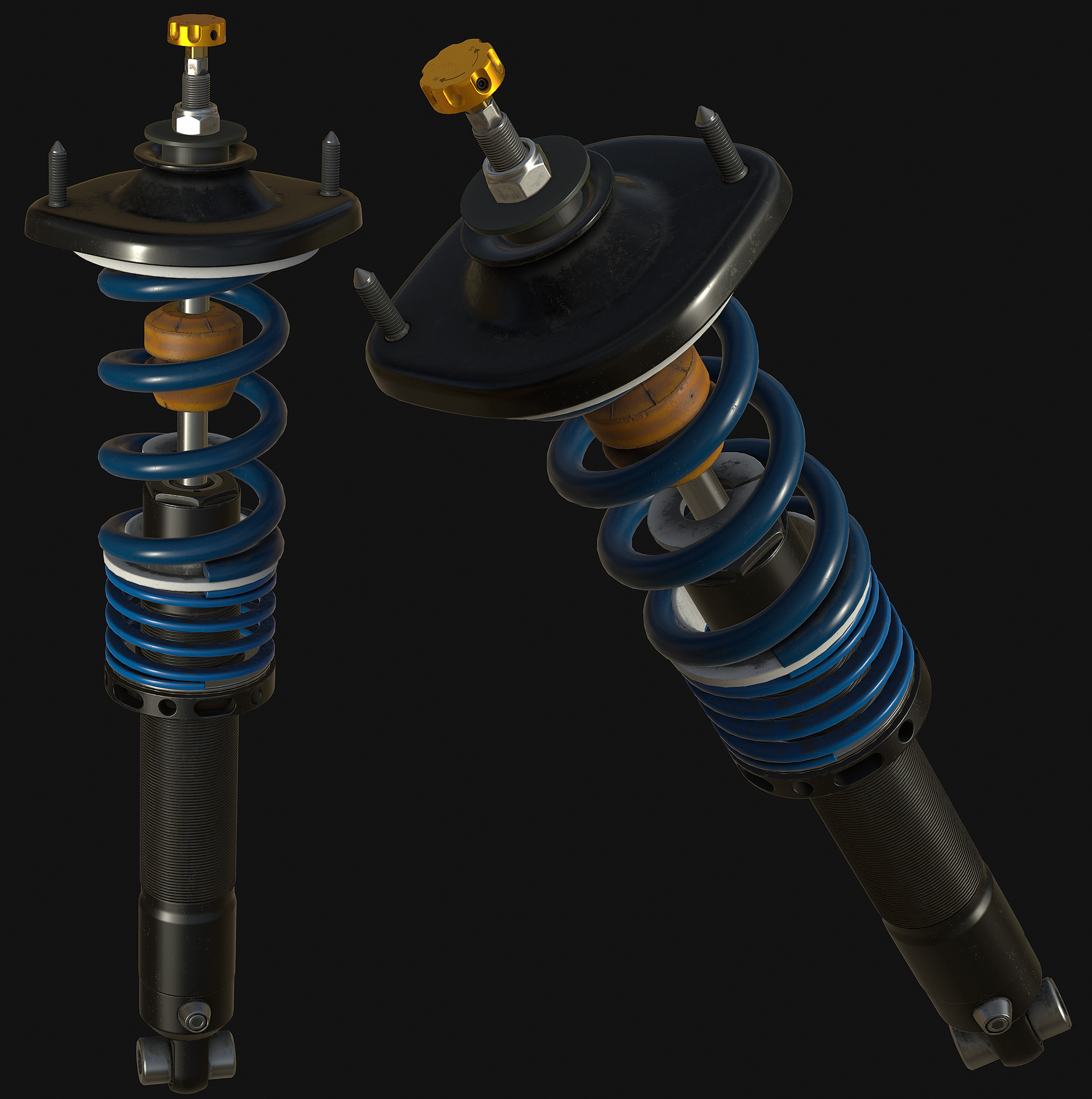
Building a car that can be fully disassembled is an order of magnitude more complicated. A car is made up of thousands of parts that need to fit and move together. These parts all sit in a giant hierarchy where Part A attaches to Part B and then Part C attaches to Part B. If the dimensions of Part B are significantly incorrect, the bolt holes may not line up, or two parts may be attempting to occupy the same space. Take, for example, the front upright. The upright dimensions are critical for suspension geometry, there are bolt holes that sit on off axis planes, and the upright mounts to a stack of other parts with minimal clearance. Here is an image that calls out some of critical dimensions on this one part:
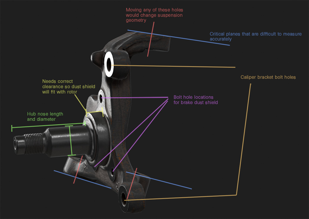
With a traditional modeling workflow I would need to take measurements and then block out the upright with a rough mesh. I would also need to do the same for all of the surrounding parts (and this chain of surrounding parts could take me through large portions of the car). In this case I would also need to accurately measure and block out:
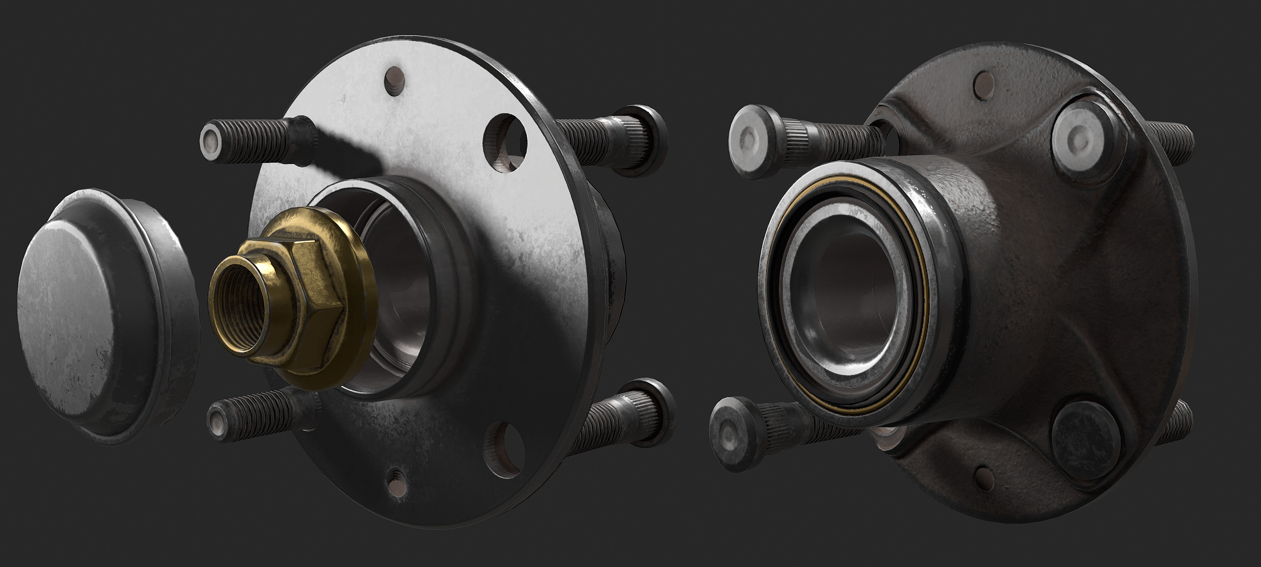
The Hub
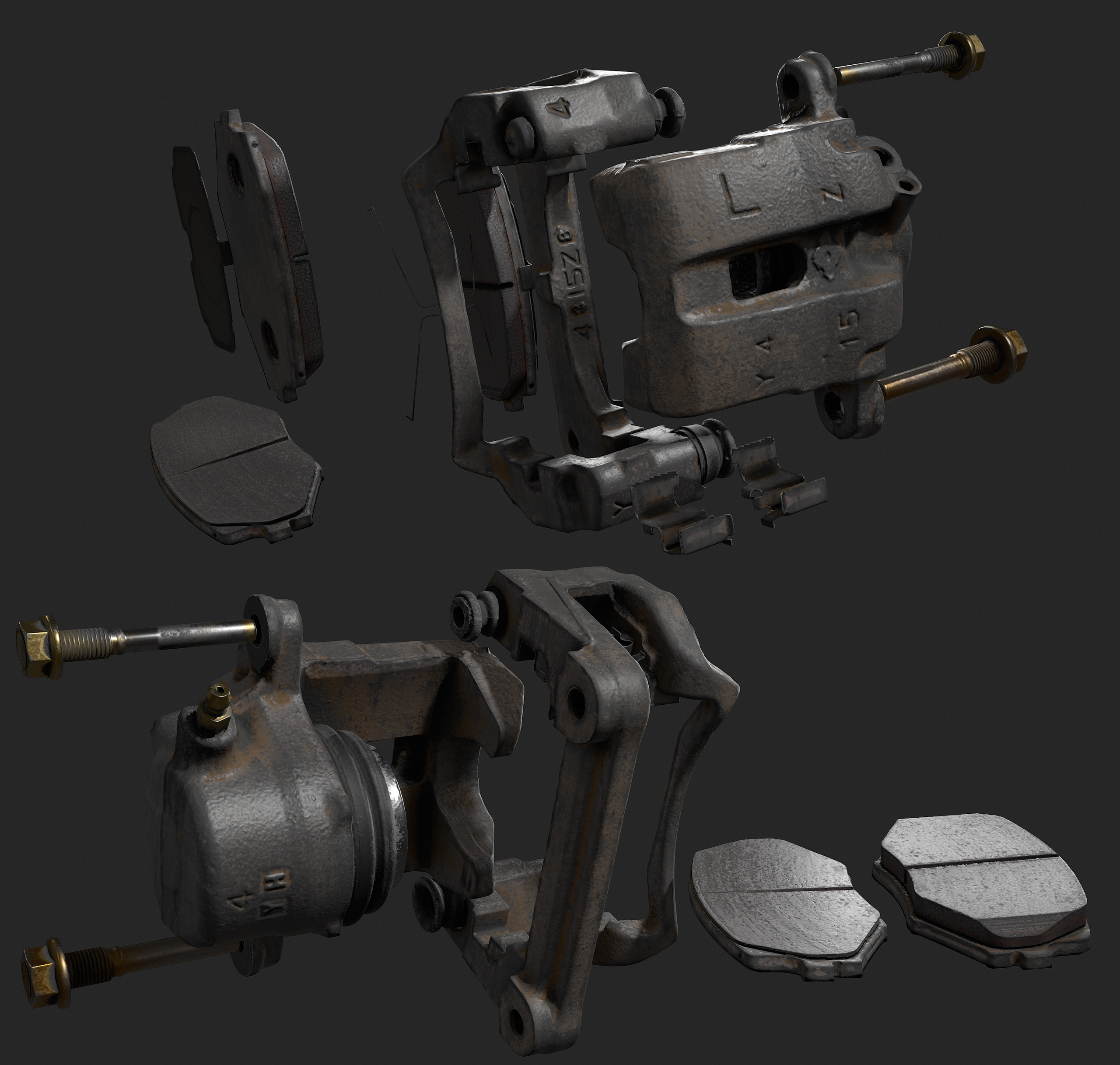
Brake Caliper Bracket
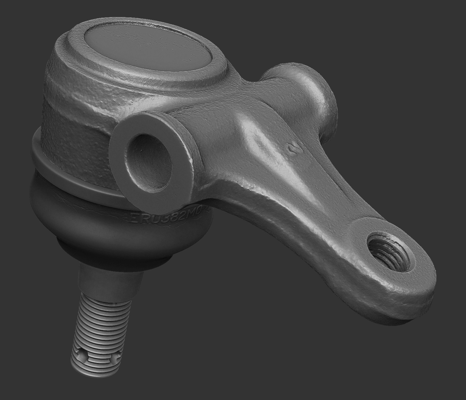
Lower Ball Joint
Tie Rod End
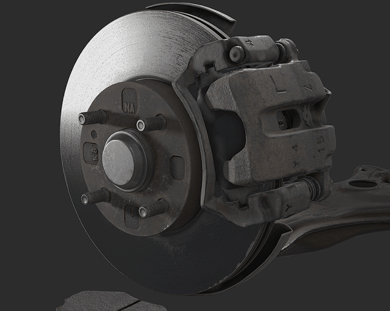
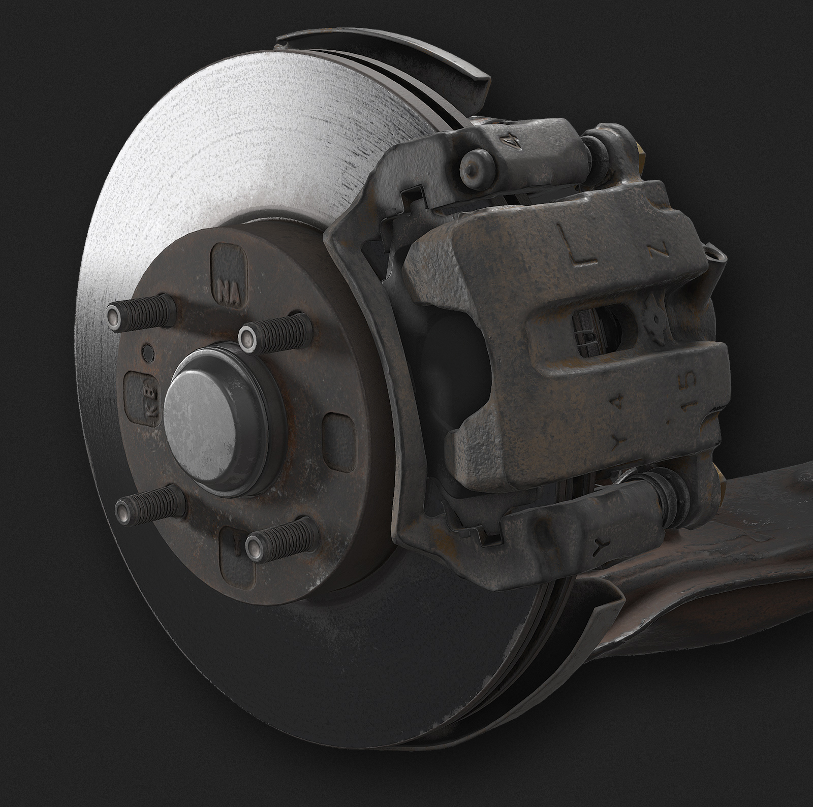
Brake Caliper
Brake Pads
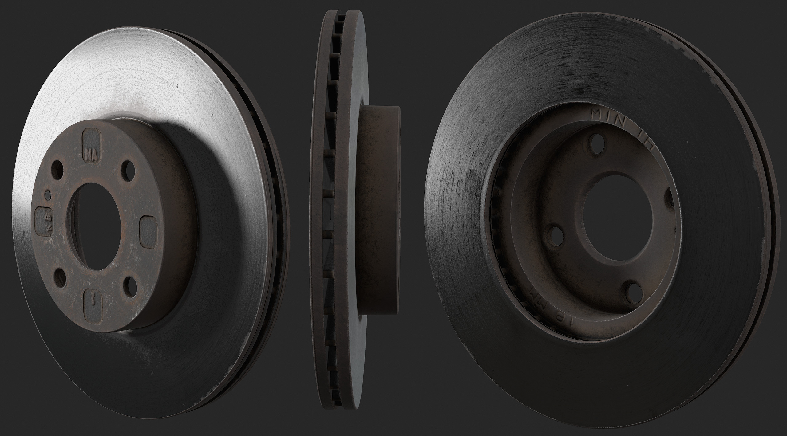
Brake Rotor
Brake Dust Shield
Front Upper Control Arm
Front Lower Control Arm
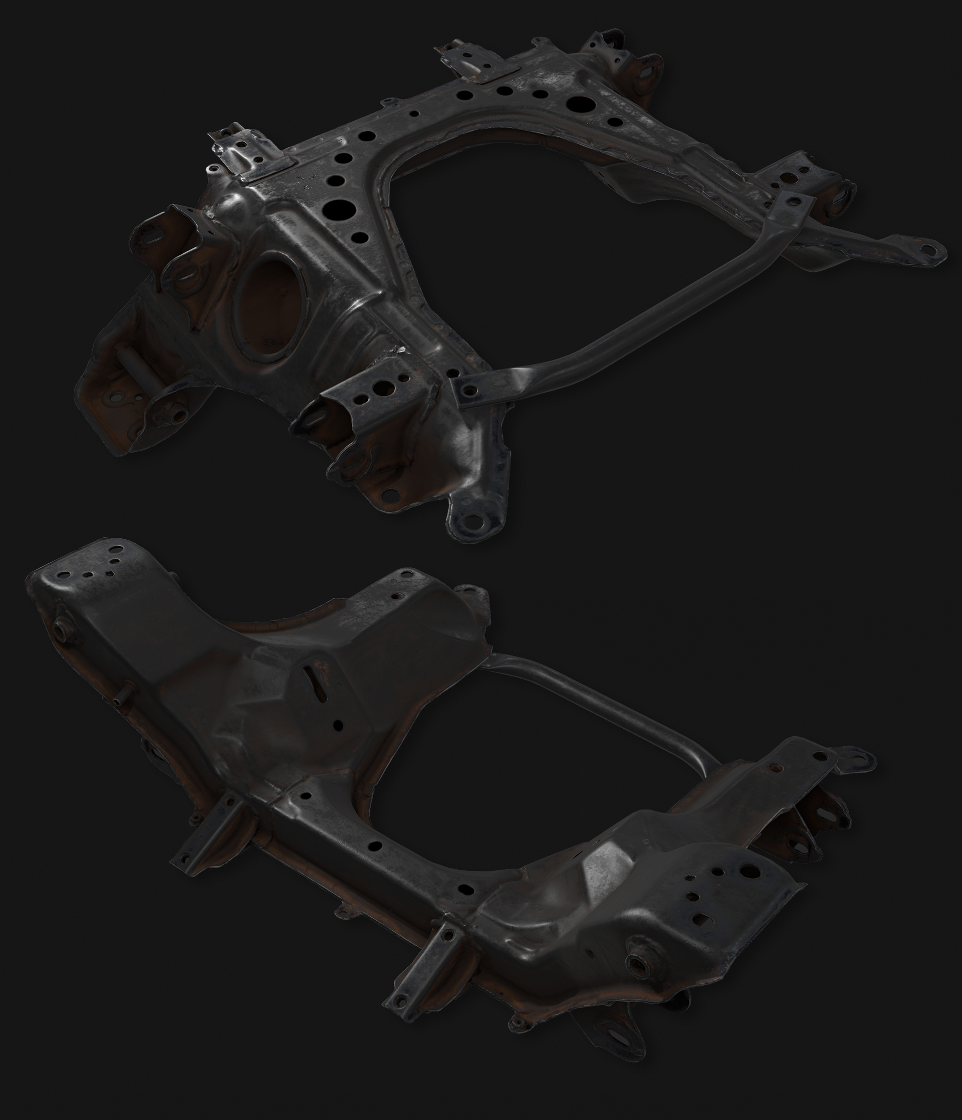
Front Subframe
Theoretically once you reach the Front subframe you need to consider where the engine mounts, engine dimensions, where the PPF mounts…but you could probably get away doing the subframe as one of the last pieces of finished art and adjusting it to fit everything else.
I couldn’t start the process of building the actual models until everything in that list had an accurate block out mesh. This game began as a part time experiment on weekends and in the evenings after work. Building a block out of a relatively complete car is not time efficient and there are too many opportunities for one incorrect dimension or block out error to propagate down the chain of parts and require rework. The need for rework might not be discovered until after several months worth of production art was completed and depending on where the error occurred, there could be a lot of art thrown away.
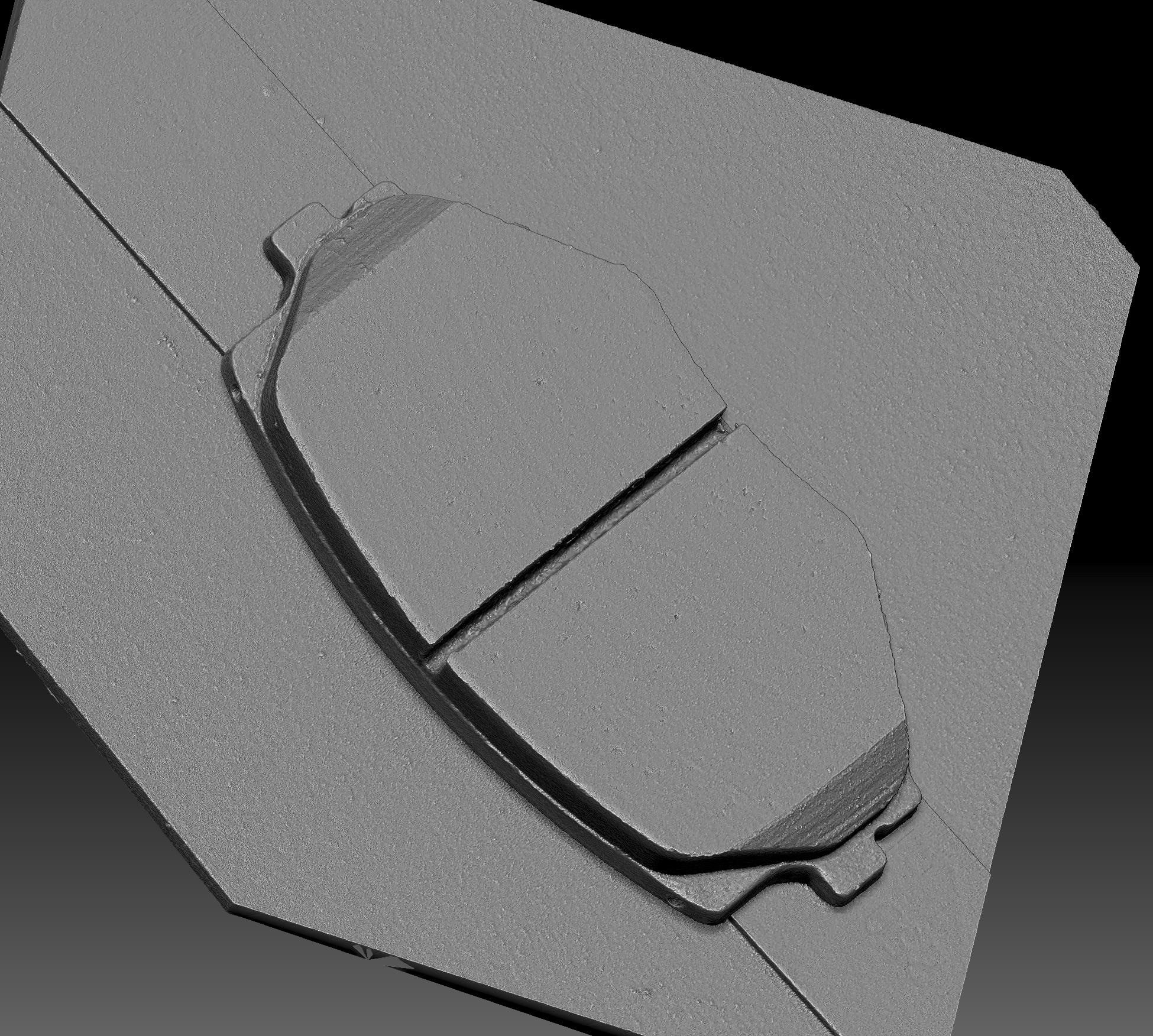
In 2015 I did some experimenting to find a workflow to efficiently build an entire car worth of parts and have it all fit together. I had some experience with photogrammetry (3d scanning from photographs) as part of the fabrication process for some 3d printed car parts. At that point, my photo equipment and software limited my results to relatively blobby but useful meshes. These could replace the need for doing block out models and I could work on each part individually while being assured that parts would fit together correctly.
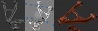
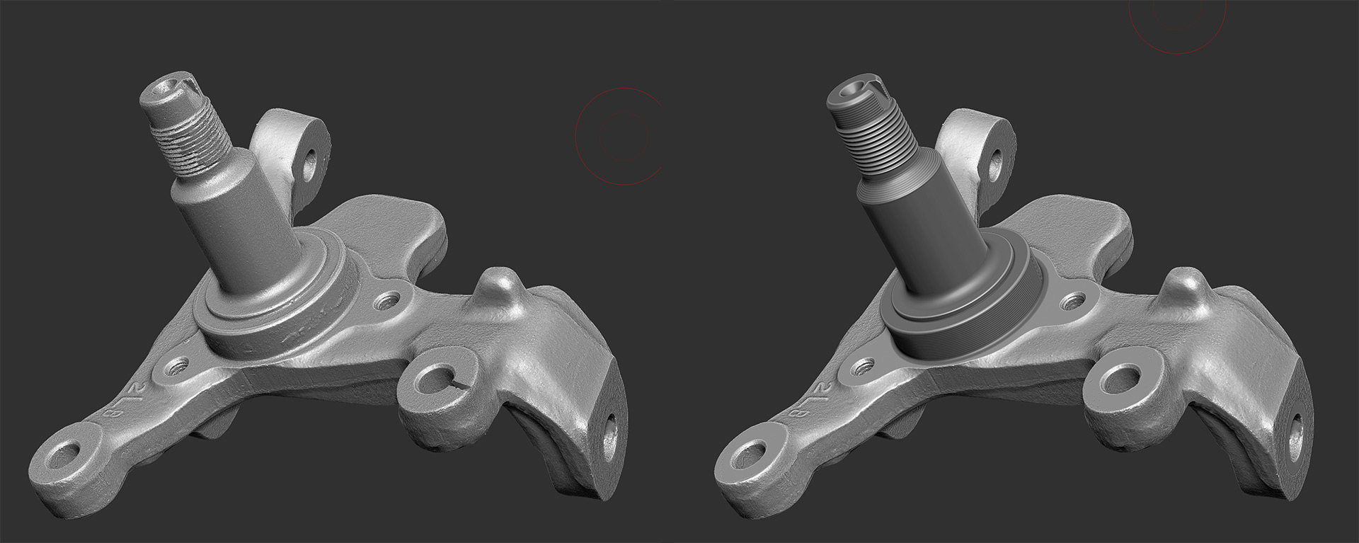
My early scanning results. Left: Scan mesh Right: A clean polygon model built from scratch using the scan as a blockout.
This worked and I was able to confirm accuracy to a tolerance that was acceptable, but building clean polygon models for all of these parts from scratch was extremely time consuming. At this point I was unsure if this idea was feasible with a team of one person working part time.
During 2016 I did more experimenting with photogrammetry in the hopes that I could efficiently produce scans that were high-quality enough that they wouldn’t need much rework. I am at what I think is my final iteration of scanning workflow and it looks like this:
*Nikon D800E with Sigma 50mm 1.4 <- this combination provides plenty of resolution and dynamic range.
*I am lighting everything with studio flash units. Switching away from continuous lighting has sped up the photography process by a factor of about 10X and every photo is now tack sharp so there are no throw away images.
*I’m treating the surfaces with Cantesco D2000A developer spray
*I switched my software to Reality Capture.
I created a tutorial covering what is effectively the same workflow here:
http://www.alecmoody.com/rubble/
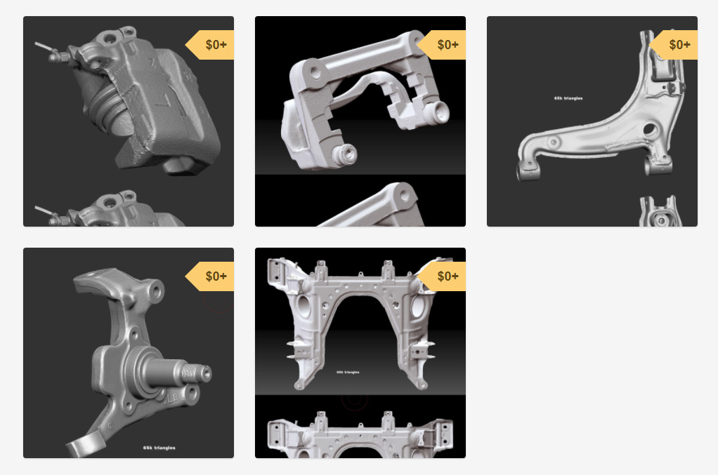
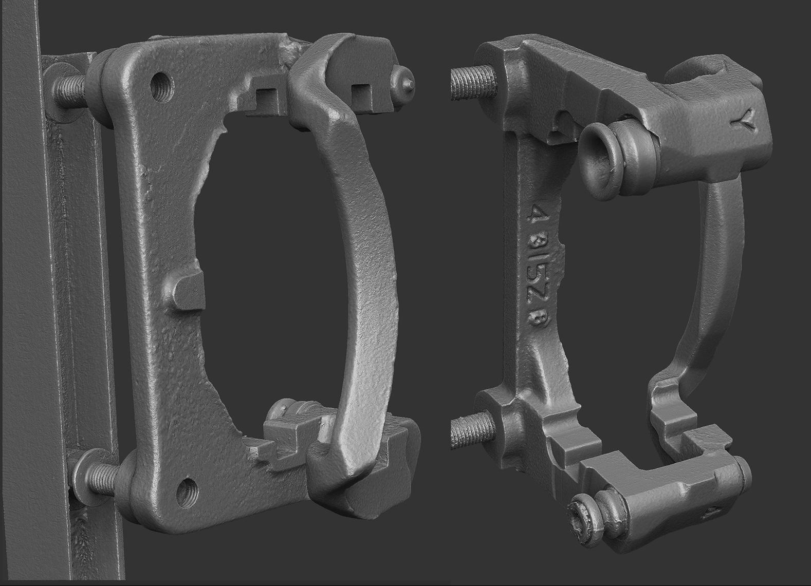
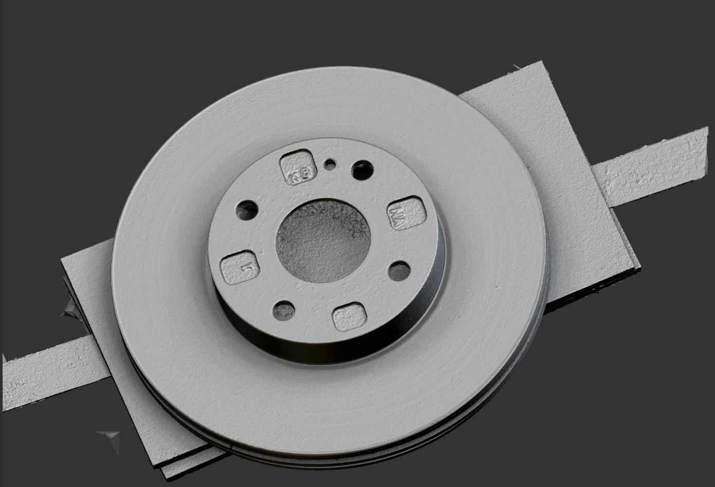
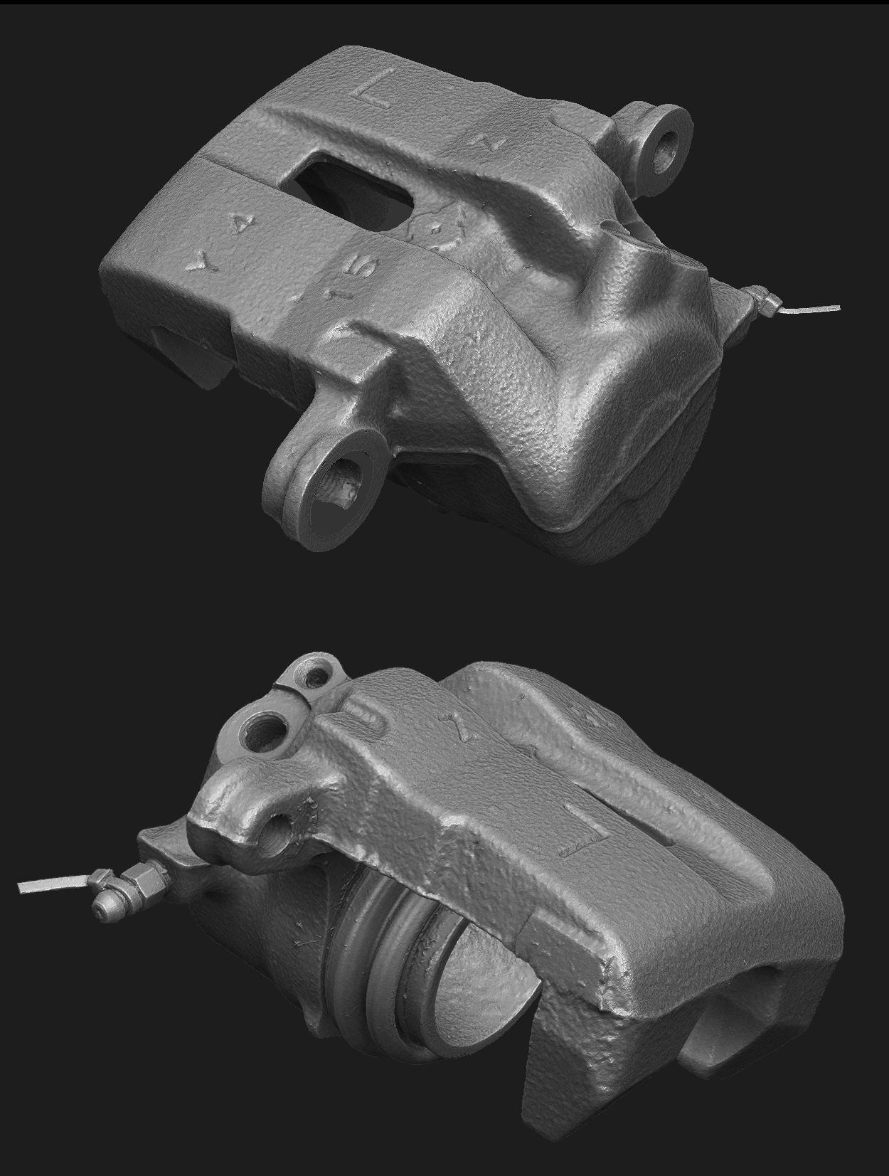
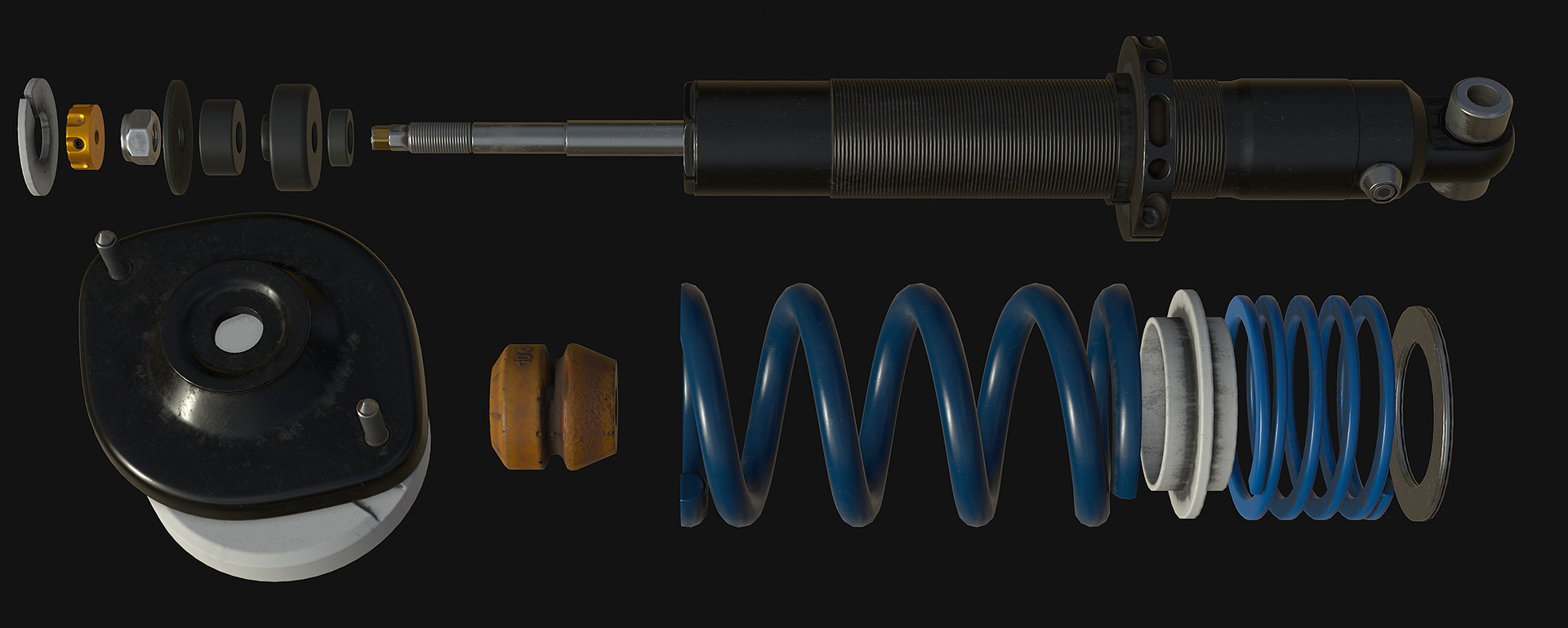
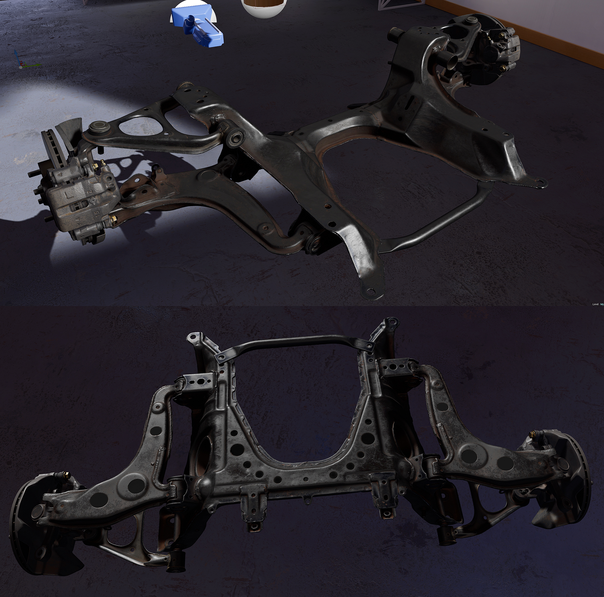
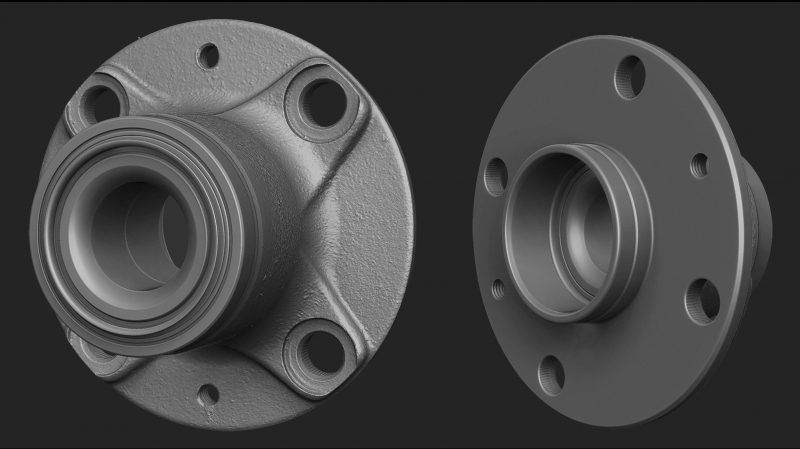
The models I get out of this scan workflow are extremely high quality but polished areas and machined pieces still need remodeling. I also don’t attempt to scan things like fasteners and instead use thread checkers and calipers to build accurate parts.
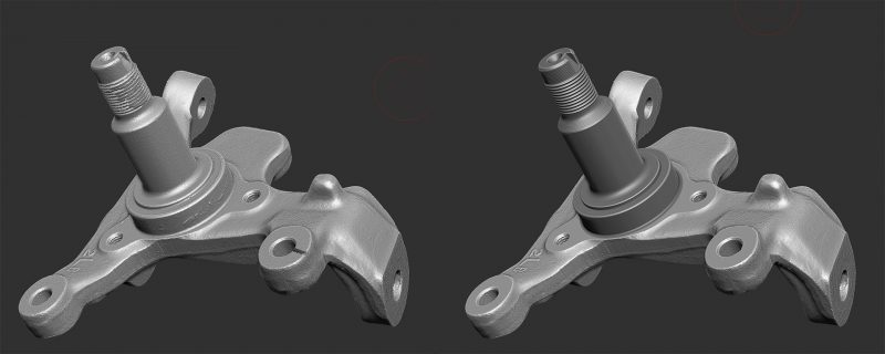
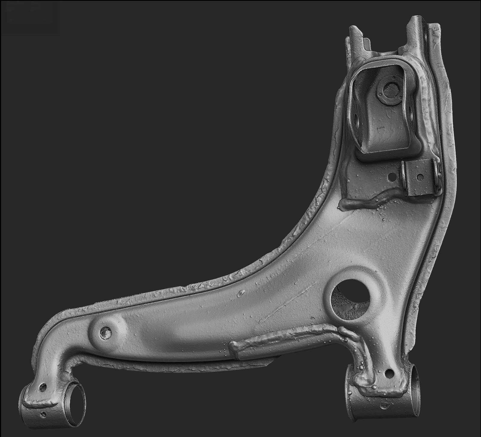
On the left, the raw scan. The casting details are fantastic but there are errors from where the object was zip tied and suspended when it was photographed, and the machined surfaces are noisy and lack detail. On the right I combined the scan mesh with a polygon model for a clean final object.
The other half of this game art workflow is taking these high res models (usually about 10 million triangles per part) and building low poly game art with materials. At some point I will do a follow up post covering that process.
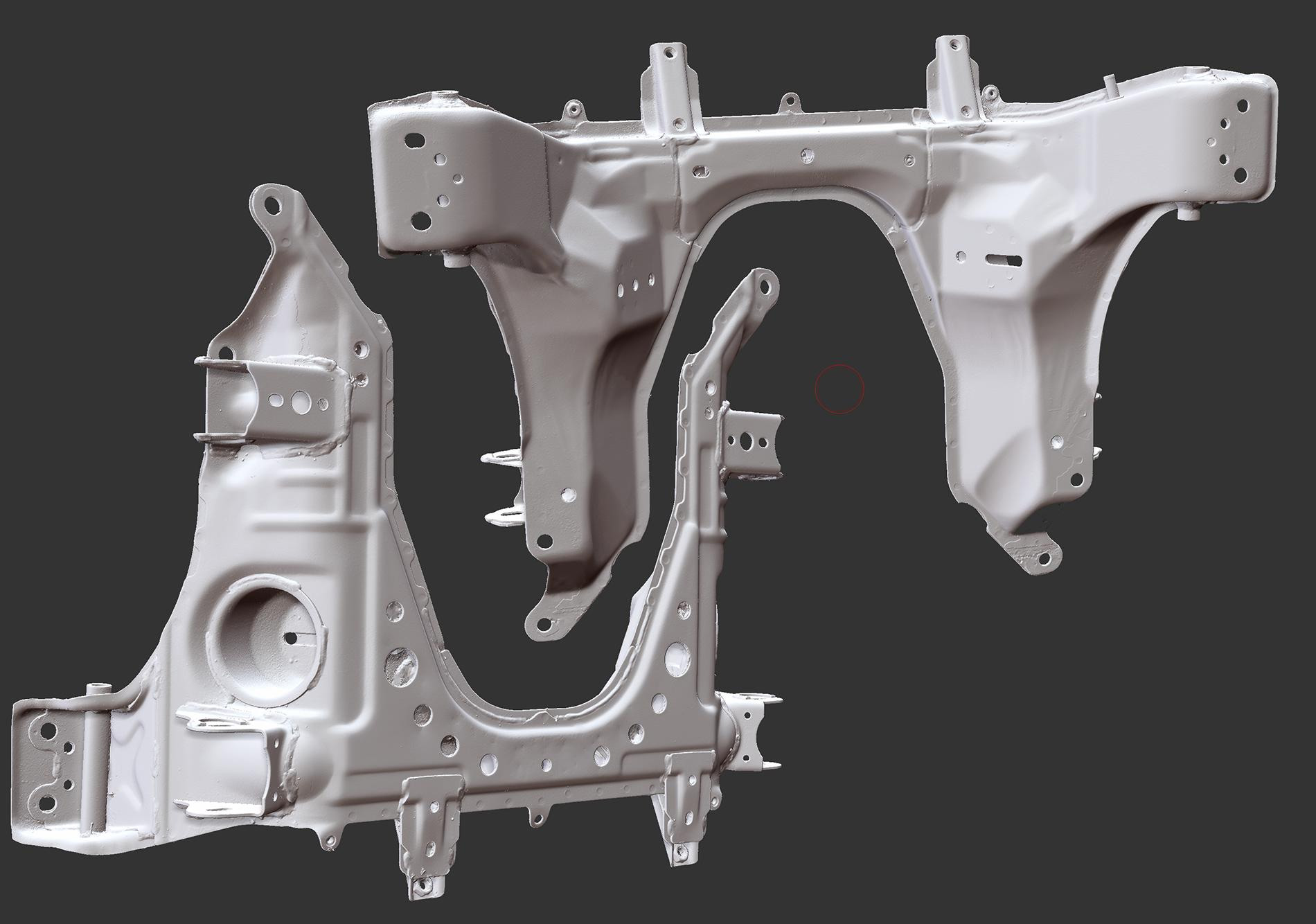
More scan results: