Wrench is now available for Early Access on Steam:
https://store.steampowered.com/app/936720/Wrench/
Join our Discord server:
https://discord.gg/G7SYSSK
View the public development roadmap:
https://trello.com/b/Yerx39XG/wrench-development-roadmap
Wrench is now available for Early Access on Steam:
https://store.steampowered.com/app/936720/Wrench/
Join our Discord server:
https://discord.gg/G7SYSSK
View the public development roadmap:
https://trello.com/b/Yerx39XG/wrench-development-roadmap
Wishlist the full game on steam here:
https://store.steampowered.com/app/936720/Wrench/
Or on the Oculus store here:
https://www.oculus.com/experiences/rift/1415202825245458/
We just launched a free demo for Wrench in the Oculus store: https://www.oculus.com/experiences/rift/1755851804523719/ This demo guides players through assembling the bottom end of the engine, timing the engine, and filling it with oil. This demo is different from the full game in a few key ways:
This demo provides high level guidance but won’t list out every part that needs to be installed or provide check boxes for every task. It is up to the player to player to read the help information and diagrams associated with every part to understand how it all fits together. The tutorial app also has a “highlight parts” button that will show you every part needed to complete each assembly phase.
I put together a few short tutorial videos to help people get started building their engine. First, make sure you are aware of the settings app. If the game isn’t running well you can adjust graphics settings (or turn them up depending on your hardware). You can also adjust your smooth locomotion speed in this app:
Here is a video on using tools successfully. There are many critical bolts inside the engine that need to be torqued to a very tight specification. Understanding how the tools work will help you get predictable results out of them:
Lastly a short video on using the part scanning tool and app together:
Wrench is coming to early access this fall. I put together this promo video that features 47 minutes of engine assembly crunched down into just over one minute
One of the big art tasks remaining in Wrench is modeling the Catfish and not having the game just be a grab bag of mechanical components. Modeling the body panels is fairly straight forward, I had CAD files for the bodywork which were reworked into clean topology for game use. The chassis was much more work. I didn’t have access to full cad for the tubes and essentially worked off of some drawings. From a technical perspective, tube chassis are a bit of a challenge for video game models. Tube structures have a lot of surface area which makes giving them unique texture space inefficient. Most of the detail is concentrated into the joints and the shock towers. I chose to split the model up into two materials, one for stretches of uninterrupted tube, and another for all of the joints and plate details. All of purple areas in this image got unique UV space so that I could sculpt the details in Zbrush:
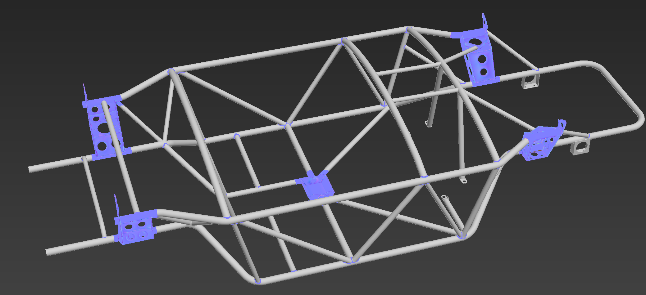
The tube material has a tiling scratch map with a down vector dirt function (dirt that faces the ground). For the details material, I have a parameter to control chassis paint color and a mask to wear the paint to bare steel on high spots.
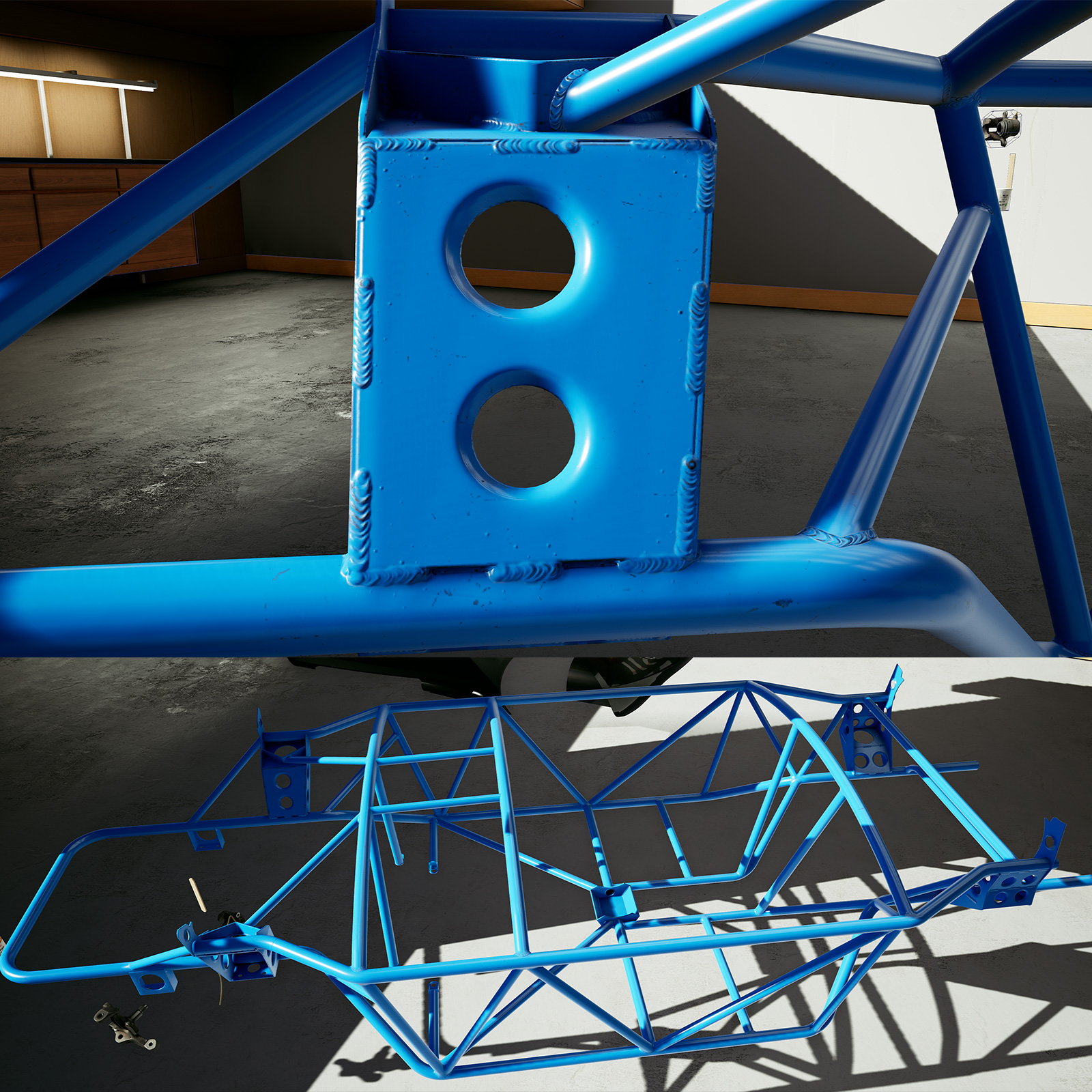
The combined result is pretty convincing. You can’t really tell that 90% of the surface is a simple tiling material and there is enough texture resolution to get good detail on the important areas.
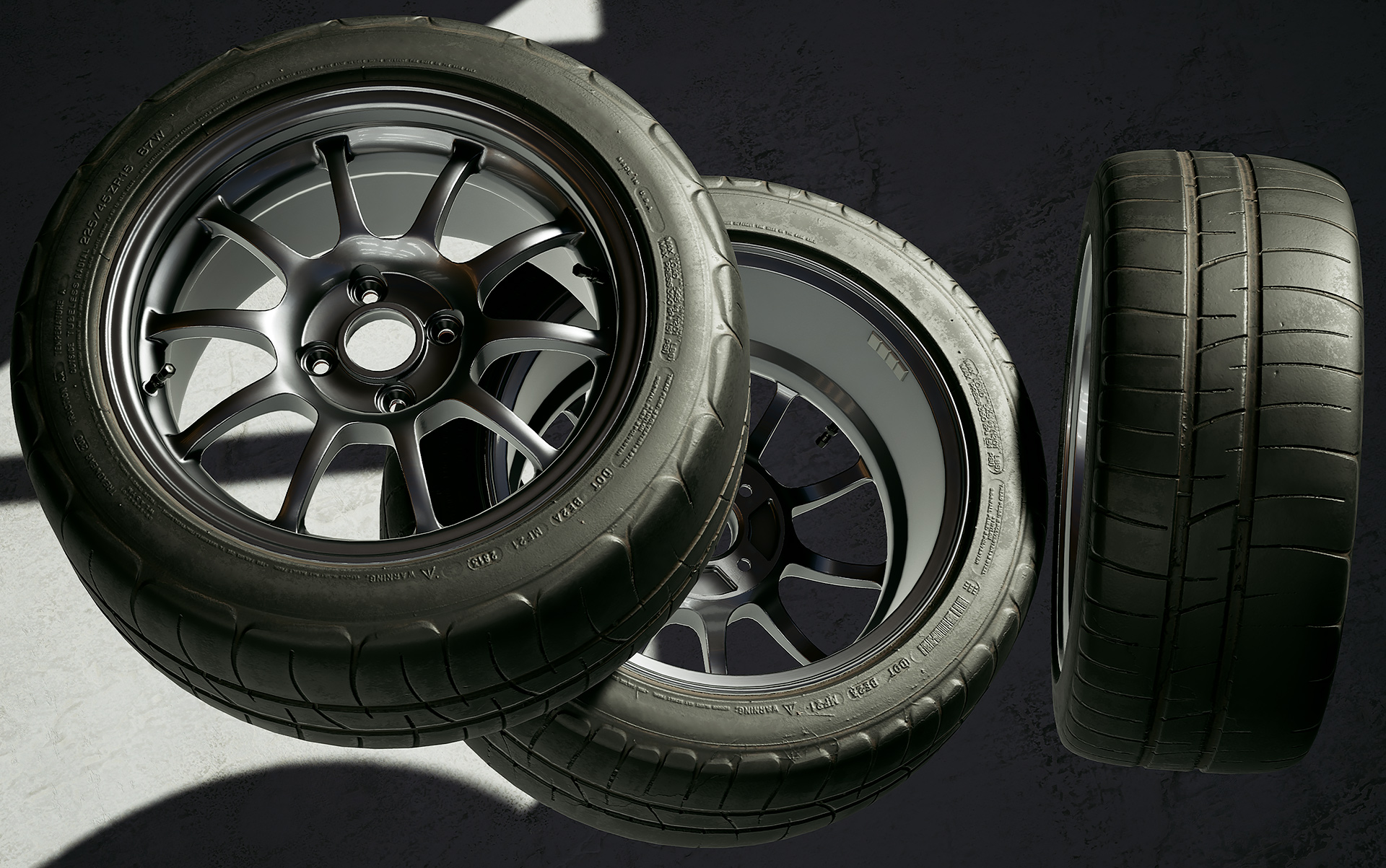
I also modeled up the first set of wheels. I tried to keep the wheel design understated. I think this is about as simple as a 10 spoke 15×8 +35 design can get:
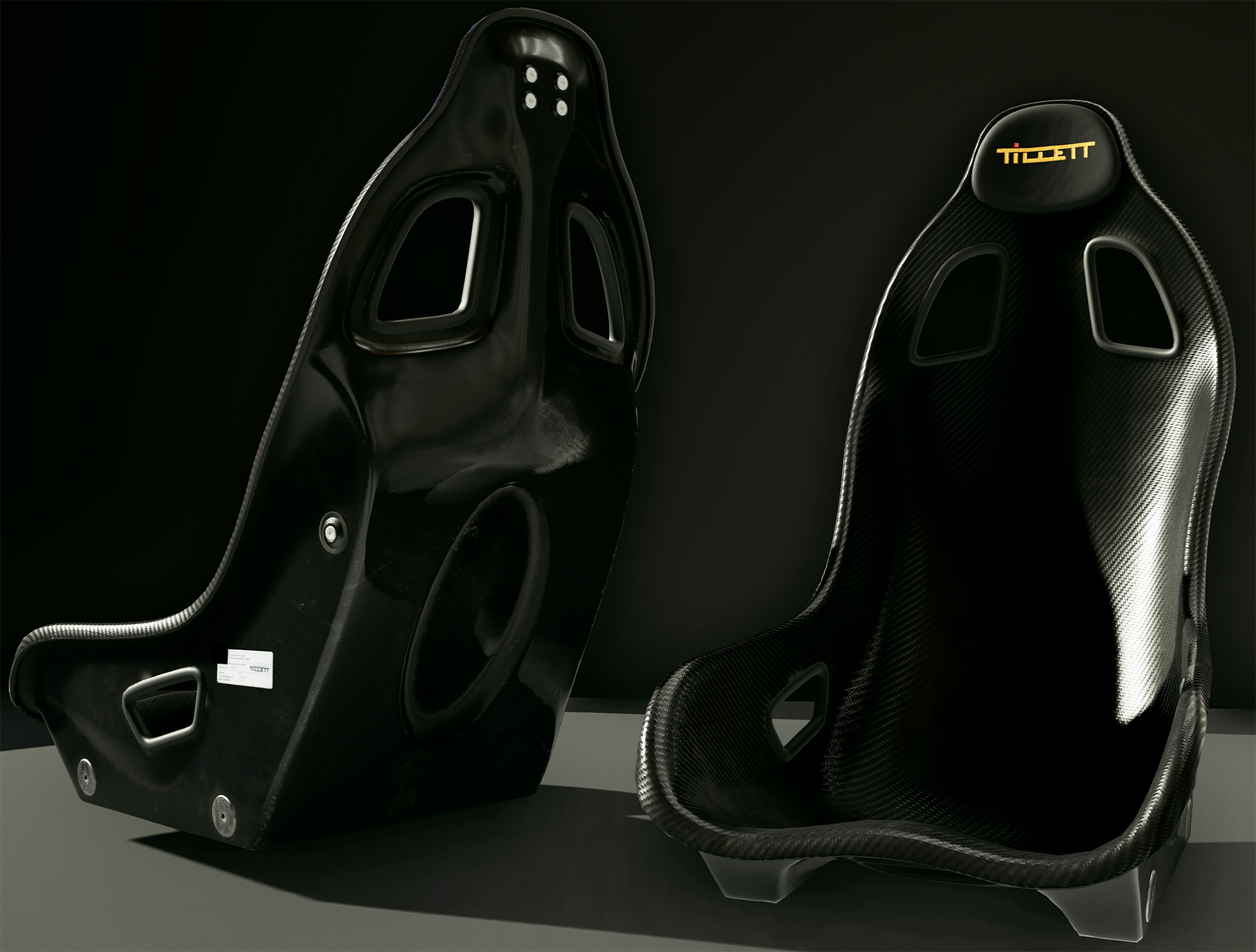
Lastly, I also licensed Tillett seats for Wrench. I have a Tillett B6F of my own and am excited they will be in Wrench. I’m planning to add more seat models as development continues:
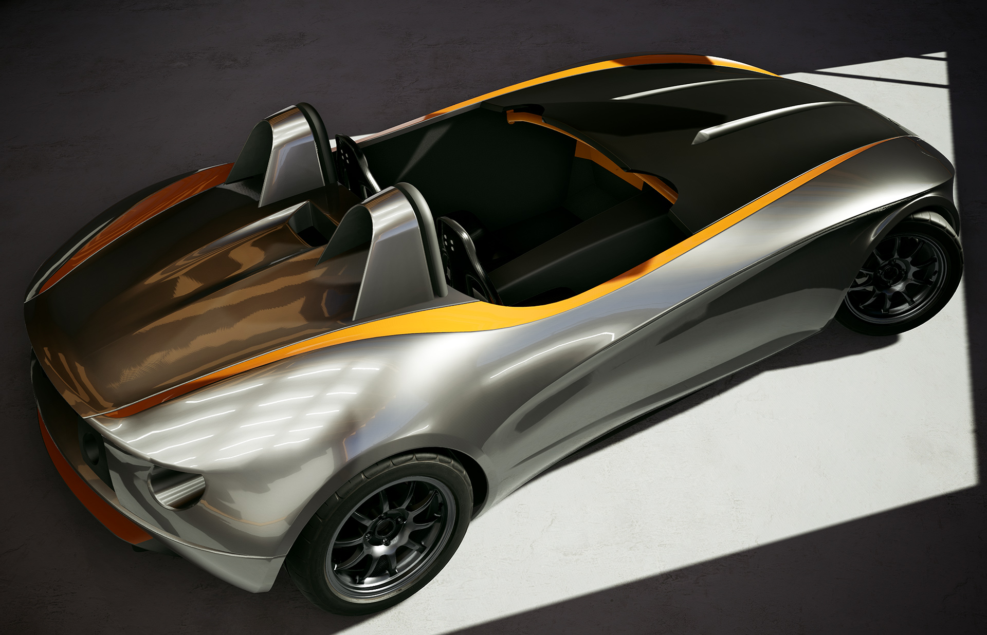
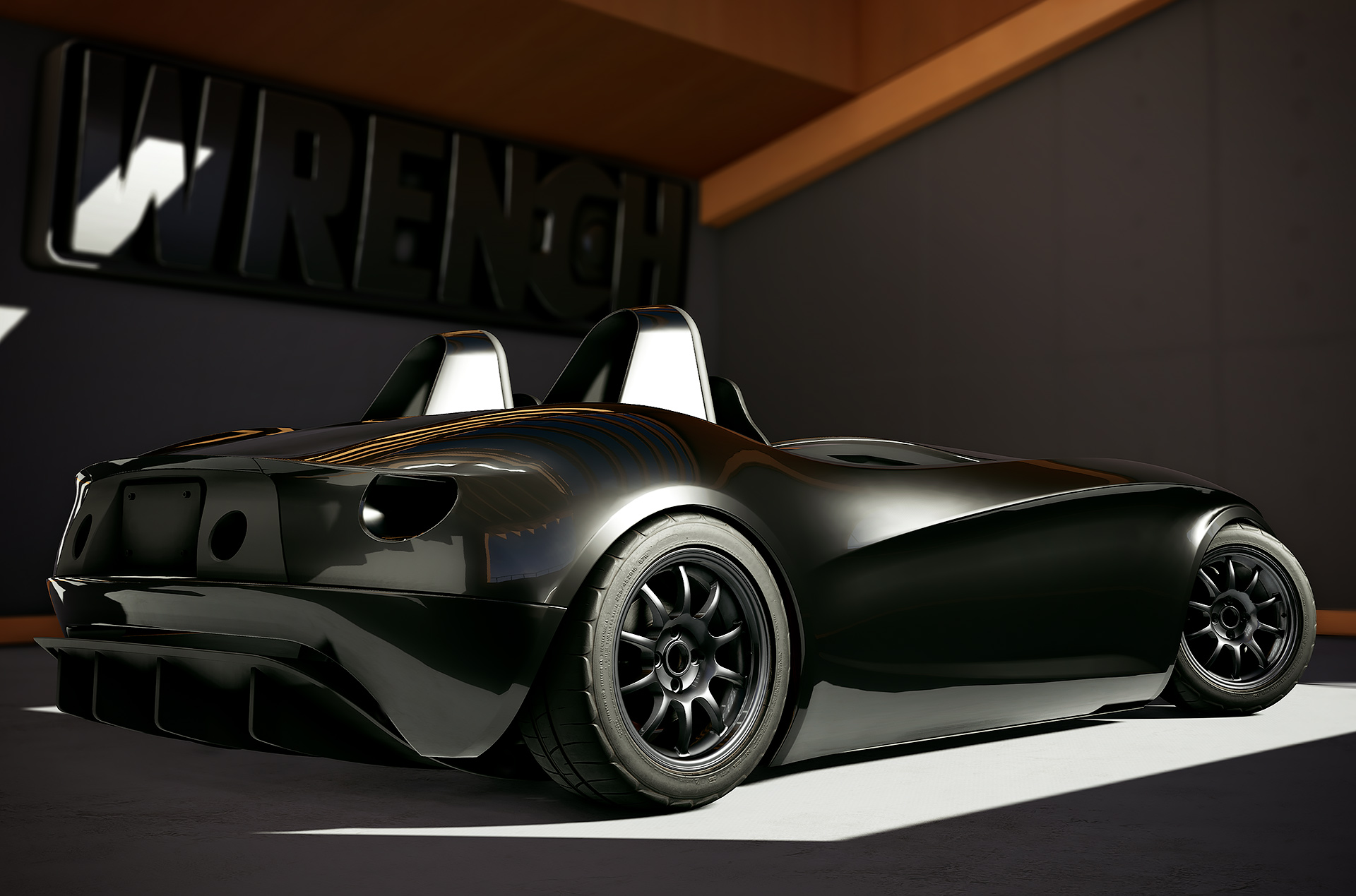
Finally, here is the finished Catfish along with a few development images. I still need to add a few details like the steering column and radiator mounts, but that will wait until I have those parts built:
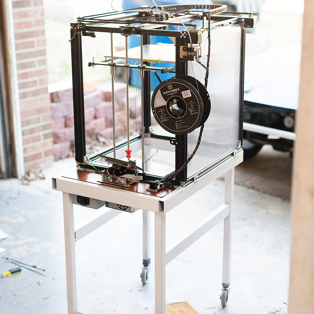
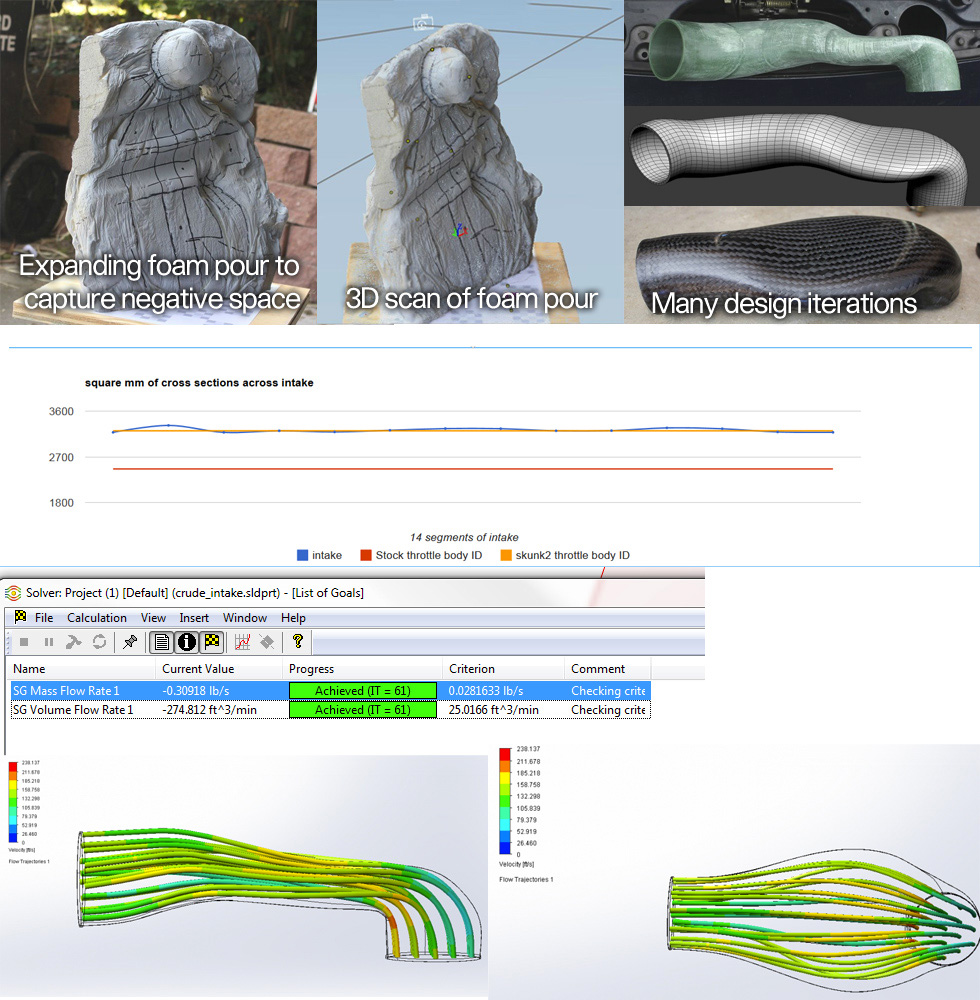
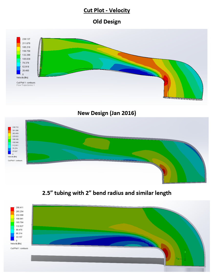
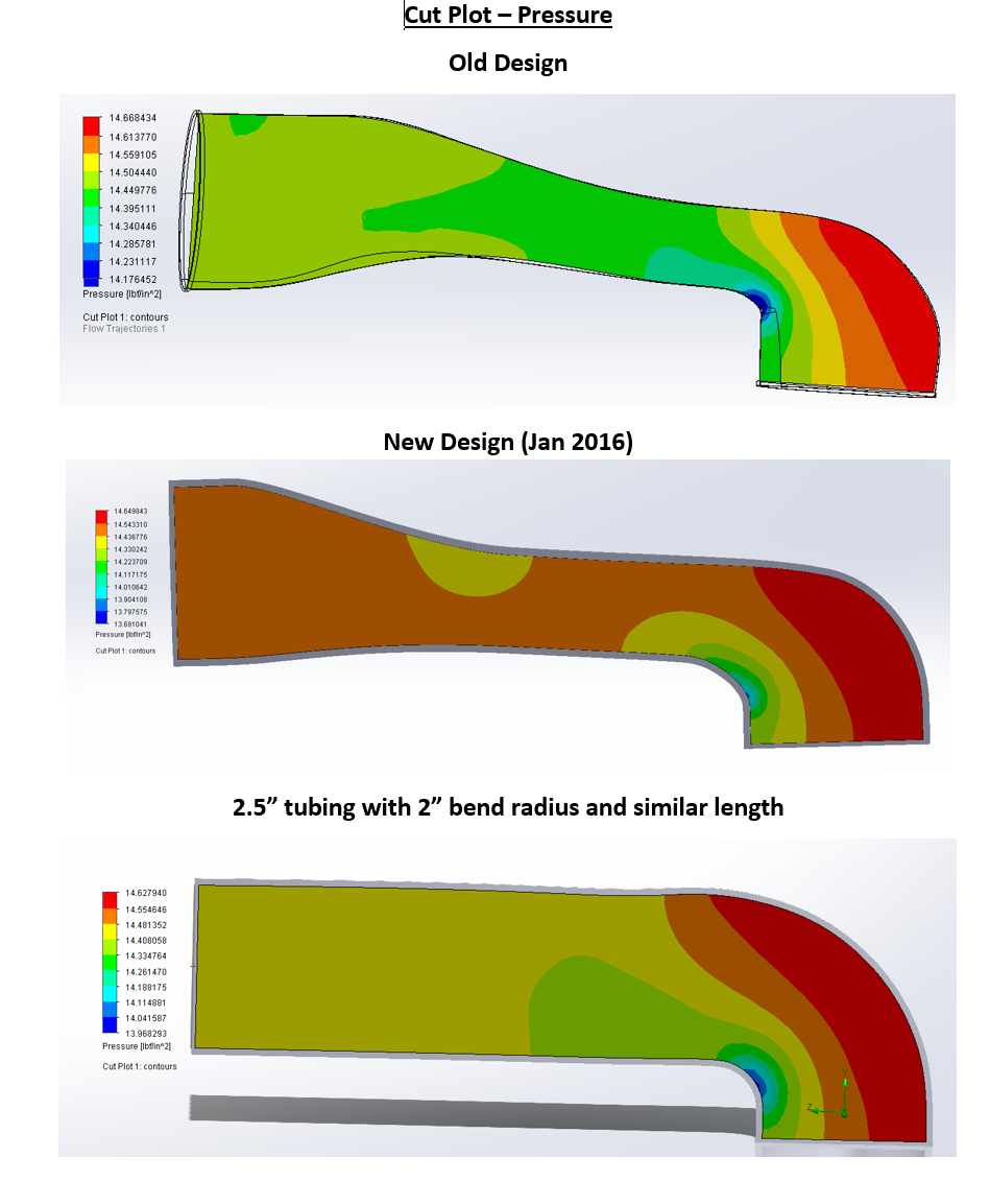
Earlier in the year I had planned to start 3d printing air intakes from my updated duct design. CFD on this design says it flows much better than the older version- This is in part because it was designed around thin walls and making use of all of the available space gained when downsizing from 3mm walls to ~1mm walls. ABS on the old parts has been marginal, heat soak, hot climates, and track use could push ABS past it’s TG and cause it to melt. To solve that problem and build more robust parts, I started building a 3d printer for engineering plastics with the intention of printing the ducts out of straight polycarbonate (150c tg, impact resistant). Polycarbonate is difficult to print, especially with large thin wall structures like this duct. I have a half built printer and all the parts I need laying around, but for the foreseeable future I am working crunch hours Wrench and have no time to devote to other projects.
Some details on that printer and what I was planning to do with it:
The printer started as a tronxy X5s and the following parts are either installed or waiting until I have time to install them:
*750w AC silicone heater mounted to a mic6 aluminum build plate
*Duet Wifi control board
*Bondtech BMG extruder
*E3d Volcano hot end with titanium heat break water cooling
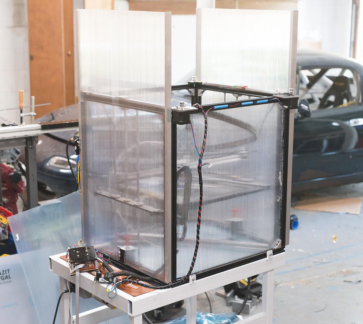
*Twin wall polycabonate chamber enclosure, intended to reach 80-90c chamber temps
*Replace XY linear motion with hiwin rail packed with high temp grease
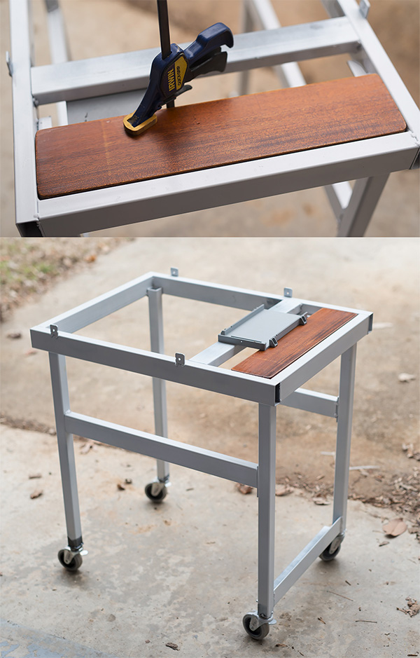
*Mounted on a custom steel cart
*Ducted exhaust run through an air scrubber to the outside. Inline fan creating small amount of negative chamber pressure to keep fumes under control
*1000w heating element for chamber air
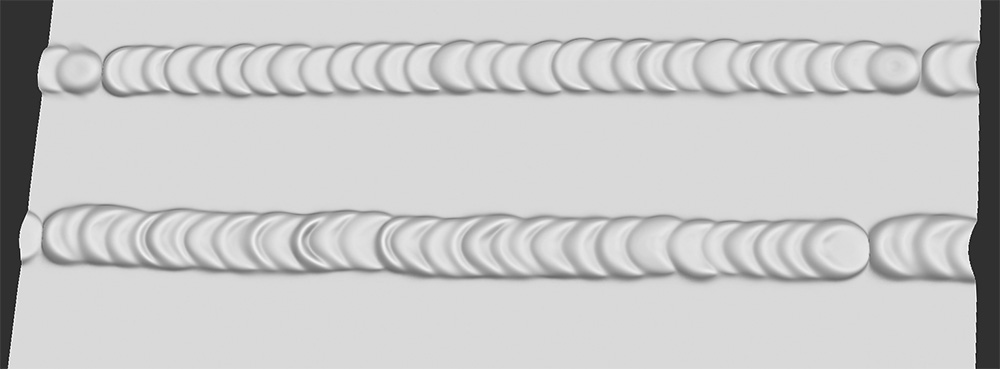
All of this info about my half built printer should be a good indication of how this part needs to be printed. Attempting to print it in PLA will result in failure. ABS is will be marginal and fail in some applications. Heat soaked engine bays can get very hot. Printing high temp plastics is a battle against warp and layer adhesion, high chamber temps help with both which is why I was designing a printer around ~90c chamber temps.
Get the files to print here:
https://www.thingiverse.com/thing:3001440
It’s been a while since I posted an update, in part because there has been so much happening with Wrench behind the scenes. All good news. In March my friend Jim Ashcraft, formerly lead core engineer at Boss Key Productions, joined me in working on Wrench full time. Since bringing on Jim, progress has really picked up and I’ve been able to stop making artist code and focus on making content. In the coming months I’ll be posting details about new and improved gameplay systems that Jim is working on. For now, here’s some of the new stuff in Wrench:
Size-based part movement smoothing. This eliminates twitchy behavior and helps give objects a sense of weight.
More advanced install behaviors: Parts that are installed along a linear track (valves, fasteners, crankshaft, etc.) slide into place.
New tool features: Electric ratchet and torque wrench functionality. Tuning to feedback is adjusted to give players a better sense of bolt tension. Maximum force a hand tool can generate is based on handle length–use small tools for small fasteners.
First pass at saving and loading system.
2d mode: Play Wrench without VR, switch between VR and 2d-mode without leaving the game.
The second big piece of news is what enabled the first: I signed a deal with Castrol/BP to brand the lubricants in Wrench as Castrol products. For consumers this means two things: First, previously generic bottles of fluid will now be Castrol products; and second,I was able to hire Jim and you all get a better game sooner. I’m not required to push Castrol products or do any advertising for them outside of branding the products in the game. That said, Castrol should be commended for taking a risk on a small developer and I’m happy to have their support. Castrol makes high quality products and they have a long history of supporting motorsports.
Finally, my business will be operating under a new name: Missing Digit. Unfortunately, I set up my company with the original name, Digital Mistake, just weeks before another developer became visible when Steam did their mass game approval last year.
A video with some recent Wrench progress:
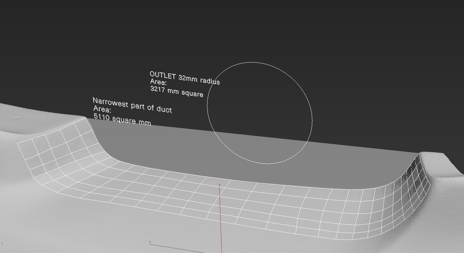
Working with my friends at SADfab I designed some brake cooling ducts to fit into the popular Garage Vary lip for the first generation miatas. Like my air intake design, the first step is to do a 3d scan and find out what space constraints I was going to be working with. The duct exit needs to be a 2.5″ OD to work with common 2.5″ silicone cooling duct hose. After a scanning, some quick measurements show that there is more than enough cross sectional area at the smallest part of the duct opening:
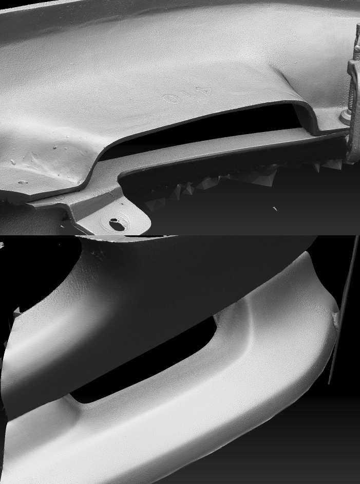
The first step was to print a test piece in order to verify the accuracy of the scan:
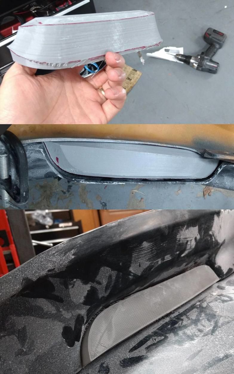
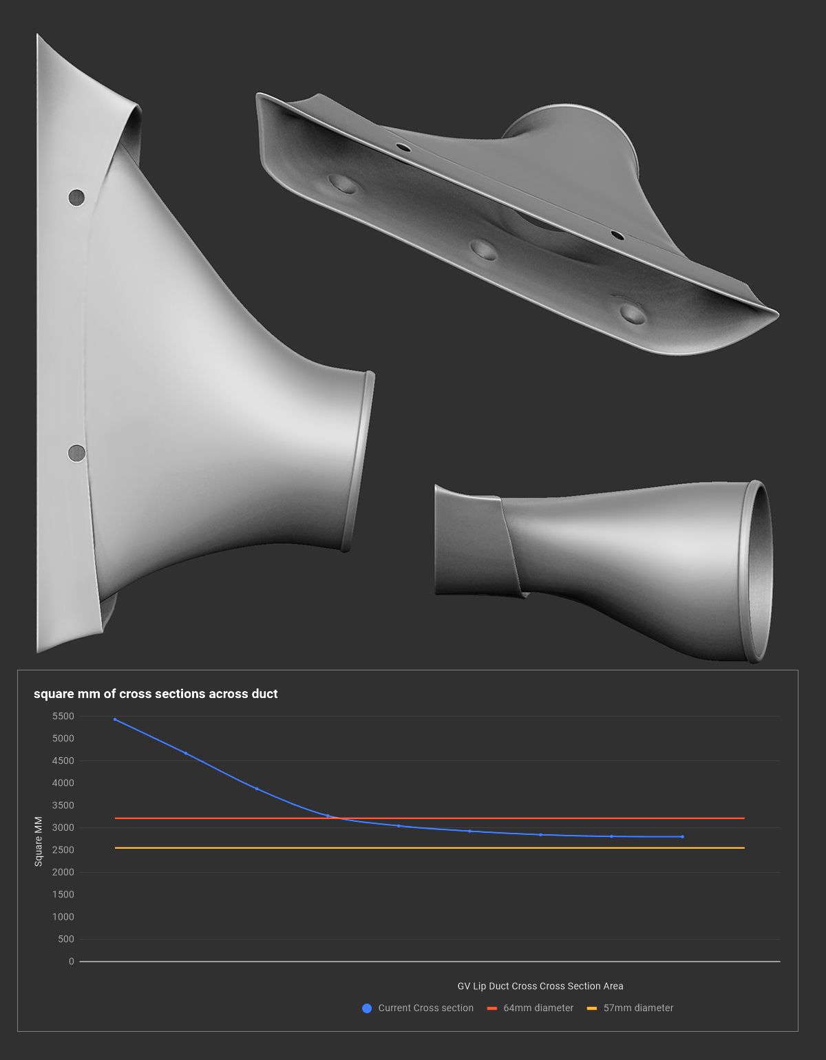
After verifying the fit, I mocked up a few different designs. This part is much more straightforward than my air intake system since there is no bend involved, and it’s not packaged into nearly as small of a space. In order to perform well the duct needs to do a few things:
1) Smooth transition between different cross section shapes. Abrupt changes in the surface can lead to turbulence in the flow path.
2) Create a continuous taper in cross sectional area from the large opening to the smaller 2.5″ outlet
3)Provide a positive fit into the bumper opening
4)Come up with a solution to mount the duct into the bumper and lip.
I settled on a dual wall design where the outer wall of the lip is a direct fit for the bumper, and the inner wall acts as the flow surface. For mounting I decided to use m5 countersink bolts with nylocks. In order to reduce the effect of intrusions into the air stream, I created raised bosses for the counter sink hardware and then blended them into the flow surface.
![]()
SADfab should have kits for sale soon. More information on their facebook page:
https://www.facebook.com/SADFab-1750837611860022/
Over the last few weeks I have built up the gameplay systems for tools and fasteners in Wrench. I talked briefly about what my plans were for the fasteners in my last post, but now that the systems are finished I can show it off in detail. This video is an overview of how both the ratchet and the fasteners function in Wrench:
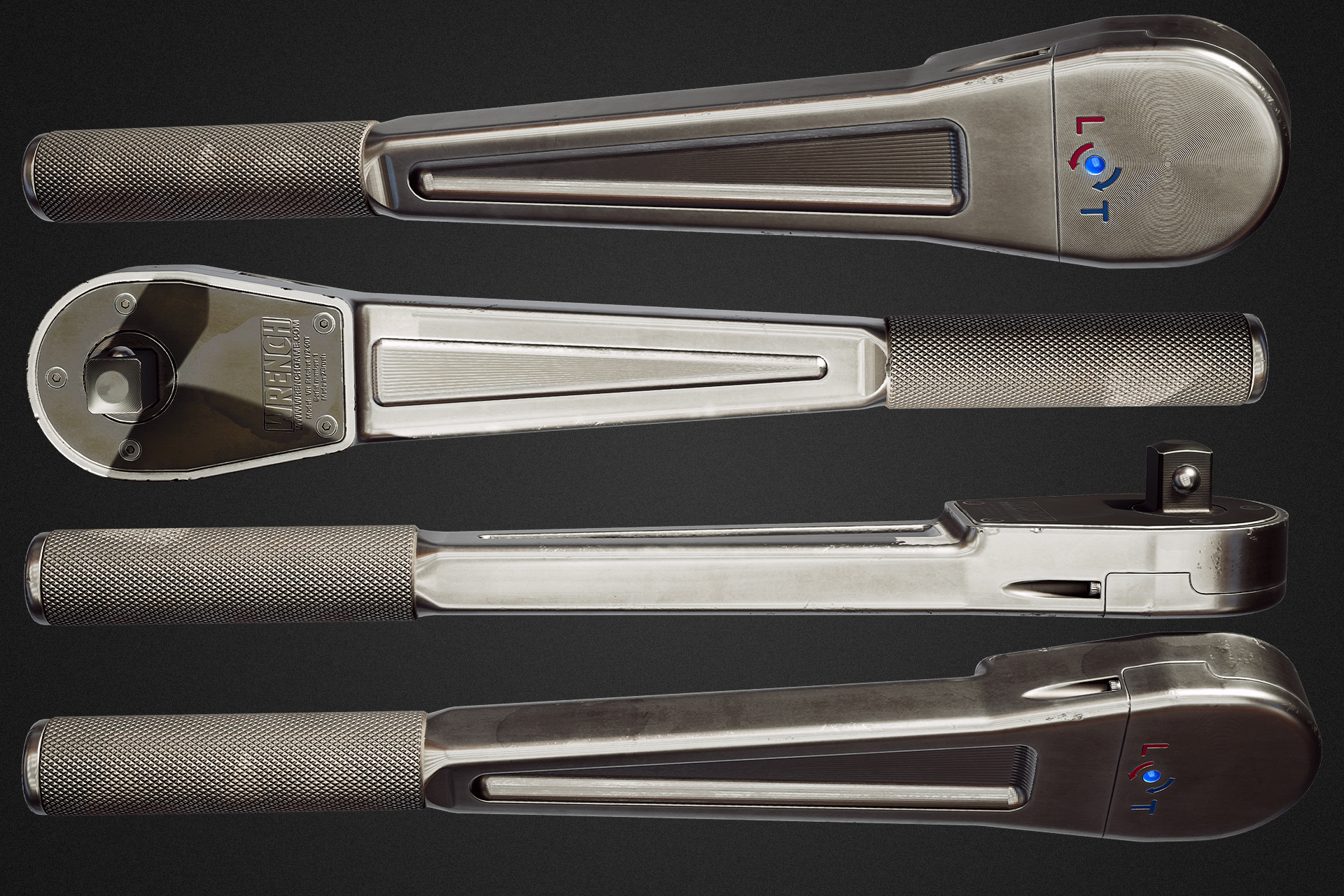
The Ratchet.
I designed a 1/2 drive ratchet that borrows the chunky silhouette common on ratchets from the 1930s and 1940s but with a modern machined look. This image is an in game capture dropped onto a background in photoshop.
From a gameplay perspective, a ratchet is a great starting point for developing other tools. With only a few changes, the ratchet code can be re-purposed into a combination wrench, a torque wrench, or an impact gun. Some of the interesting gameplay features in the ratchet:
Fasteners
In my last post I spoke about the art for fasteners. To recap, I build them with correct dimensions, including thread pitch. Since I have that data for every fastener I use it to accurately simulate fastener functionality. In my final implementation, fasteners are simulated in 5 phases. I will be using joint analysis software to generate accurate curves for ever fastener:
In addition to building art content for the cylinder head I have been working on improving the systems for part assembly and I have begun building the fastener object class so that I can start implementing tools.
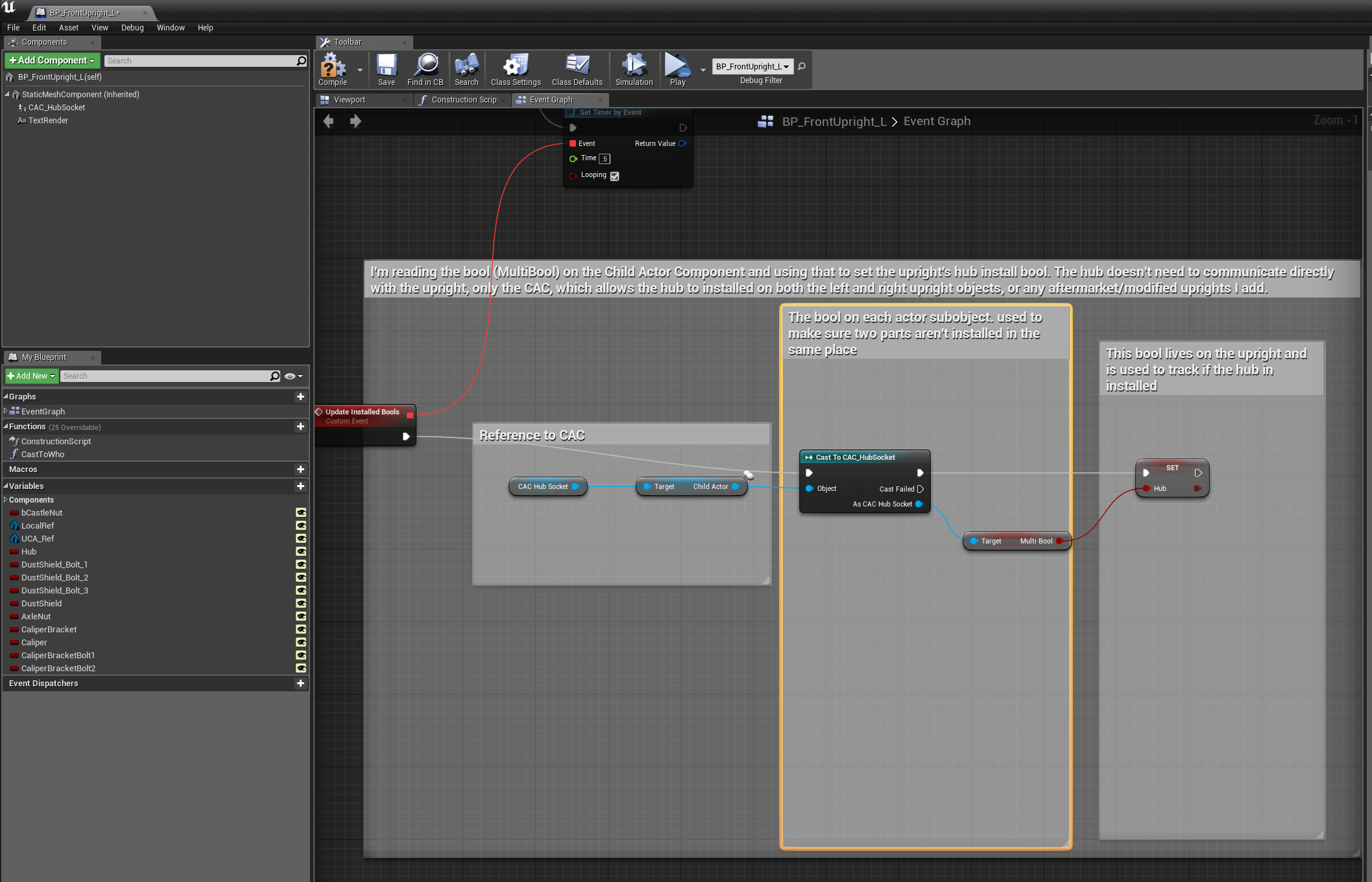
For my assembly systems I have been working on a flexible way to allow a single part to be installed in multiple locations. This will be used for most fasteners but there are also many other parts that should install into many locations. I had a simple system in the prototype video but it wasn’t flexible to cover all use cases and this new system is much more robust. The trick to making a single part snap to multiple locations is both setting is both doing the actual part snap, and making sure you have a system to correctly store bools in order to run logic around install status. I’m using Unreal’s socket system to snap parts together- A socket is just a transform, there is no way to query a socket and see if it is occupied. If every single part in an assembly is unique and can only be installed in one location, you can simply make a bool for each socket, and then set the corresponding bool when a part is installed or removed. If you don’t actually know what object or what location on an object a part was installed, managing the bools becomes more challenging.
The solution I have come up with is using an intermediary Child Actor Component (CAC) any time I want one part to attach to many locations. A CAC is an instance of a blueprint that is spawned as a child object at run time. In my use case, each CAC is just a null static mesh (cube with visibility turned off) that has a socket I can snap to, and a single bool to indicate if that CAC slot is occupied. In this example, the hub object can snap to either the left or right uprights. The hub is actually snapping to the CAC object that each upright contains. The hub doesn’t need to communicate with the upright- On install/removal it only changes the bool on the CAC (called MultiBool). The upright is then responsible for checking the CAC, reading the status of MultiBool, and then settings its own hub installation bool to match MultiBool on the CAC. I’m checking the CAC for it’s bool status once every .5 seconds, I could probably make the check even less often since that bool isn’t actually used by the hub for it’s install or removal logic.
Here is a video of the wheel studs, front hub, and uprights all using this system:
I have been prototyping the fastener object class. The fastener object class is a subclass of the main snap part class with a bunch of added information:
Int: Fastener head size. Used to automatically swap sockets or wrench sizes to fit the fastener
Float: Fastener length
Float: Fastener thread pitch
Float: Major Diameter
Bool: Is torque critical fastener?
Float: Target clamping force
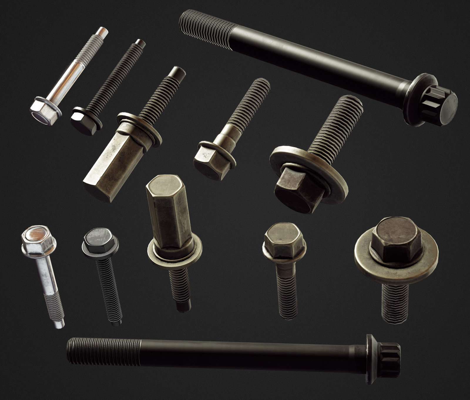
The art for every fastener in Wrench is accurate down to the thread pitch. I keep notes when I build fasteners so I know the dimensions. By including this data in each game object I can do a bunch of interesting things. First, I can make the visual representation of tightening from loose to finger tight appear accurate. If I know both the thread pitch the bolt can be moved inwards the correct amount per degree of turn added- This will make the number of turns to reach finger tight accurate. After the fastener is finger tight I can simulate an accurate clamping force based on how many degrees it is turned past finger tight, bolt length, thread pitch, and major diameter. That calculation can be re-purposed into torque wrench settings or bolt stretch gauge readings. Most fasteners in the game will not be torque critical, but they will all generate and store a torque value. I’m not planning to penalize the player for over/under torquing non critical fasteners but I can flag important fasteners (every internal engine bolt, lug nut torque, axle nut…) with the bool to see if it is torque critical and then penalize the player appropriately.
Recently finished art for the cylinder head fasteners: